
User's Manual
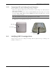
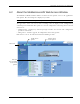
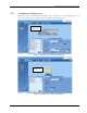
Table Of Contents
- Preface Material
- Policy for Warrantee and Repair
- General Warranty
- Specific Product Warranty Instructions
- Returns
- Limitations of Liabilities
- Reporting Defects
- Safety Warnings
- Compliance with RF Safety Requirements
- Certification and Compliance to Standards
- About This Guide
- List of Acronyms
- Table of Contents
- 1 Overview
- 2 Installation Workflow
- 3 Infrastructure Requirements and Layout Planning
- 4 VCU Unit Installation and Provisioning
- 5 VAP Installation and Provisioning
- 6 Navigating the Web Access Application
- 7 VCU Monitoring and Configuration
- 8 VAP Monitoring and Configuration
- 9 Administrative Operations
- 10 Troubleshooting
- Appendix A - Traps
- Appendix B – MobileAccess VE MIB Tree Structure (Version 1.8)

VAP Installation and Provisioning
Mixed Band LTE 700 MHz MobileAccessVE Instant Coverage Solution User Manual 41
5.2.3 Connecting VAP and Verifying Normal Operation
After the VAP has been mounted on the ceiling continue as follows:
• Connect the VAPs RJ-45 VCU connector to the Ethernet jack leading to the VCU (via RJ-45
cable supplied with VAP).
• When using an external antenna, connect the Ext. Antenna SMA connector(s) to the external
antenna(s). This option must be SW configured via the web GUI. (Note: Internal
antenna is enabled by default).
Note: The maximum external antenna gain should not exceed 10 dBi.
• Verify that the VAP receives power and connects to the VCU via the LEDs on the unit (both
the GREEN LED and the BLUE LED should be lit).
5.3 Verifying VAP Coverage Area
Verify coverage in the areas, adding and moving VAPs for optimal coverage according to the
principles described in
3.3.
Blue LED
Green LED
VAP RJ-
45 VCU
connector