
User's Manual
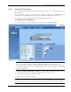
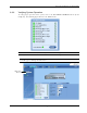
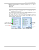

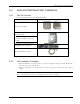


Table Of Contents
- Preface Material
- Policy for Warrantee and Repair
- General Warranty
- Specific Product Warranty Instructions
- Returns
- Limitations of Liabilities
- Reporting Defects
- Safety Warnings
- Compliance with RF Safety Requirements
- Certification and Compliance to Standards
- About This Guide
- List of Acronyms
- Table of Contents
- 1 Overview
- 2 Installation Workflow
- 3 Infrastructure Requirements and Layout Planning
- 4 VCU Unit Installation and Provisioning
- 5 VAP Installation and Provisioning
- 6 Navigating the Web Access Application
- 7 VCU Monitoring and Configuration
- 8 VAP Monitoring and Configuration
- 9 Administrative Operations
- 10 Troubleshooting
- Appendix A - Traps
- Appendix B – MobileAccess VE MIB Tree Structure (Version 1.8)

VAP Installation and Provisioning
Mixed Band LTE 700 MHz MobileAccessVE Instant Coverage Solution User Manual 40
Figure 5-3: Removing Top Rim from Rear of VAP
8. Insert the (4) VAP protrusions (on rear) in the round part of the (4) most outer holes and
pull the bracket downwards so it snaps in place. See Figure
5-4 and Figure 5-5.
Figure
5-4: Assembling Bracket on to VAP
Figure
5-5: View of Assembled VAP and
Bracket
9. (Optional) Secure Bracket to VAP with Lock by Reaching from Backside of Mounted VAP –
See Figure
5-5.
Pass lock through bracket and VAP
Remove top rim