
User's Manual
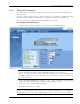
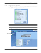
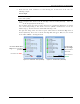
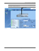
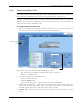
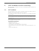
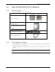


Table Of Contents
- Preface Material
- Policy for Warrantee and Repair
- General Warranty
- Specific Product Warranty Instructions
- Returns
- Limitations of Liabilities
- Reporting Defects
- Safety Warnings
- Compliance with RF Safety Requirements
- Certification and Compliance to Standards
- About This Guide
- List of Acronyms
- Table of Contents
- 1 Overview
- 2 Installation Workflow
- 3 Infrastructure Requirements and Layout Planning
- 4 VCU Unit Installation and Provisioning
- 5 VAP Installation and Provisioning
- 6 Navigating the Web Access Application
- 7 VCU Monitoring and Configuration
- 8 VAP Monitoring and Configuration
- 9 Administrative Operations
- 10 Troubleshooting
- Appendix A - Traps
- Appendix B – MobileAccess VE MIB Tree Structure (Version 1.8)

VAP Installation and Provisioning
Mixed Band LTE 700 MHz MobileAccessVE Instant Coverage Solution User Manual 39
Figure 5-1: Optional Bracket Installation Holes
3. Connect the SMA adapters and external antennas (ordered separately) to the VAP SMA
connectors. See Figure
5-2.
Note 1: The maximum external antenna gain should not exceed 10 dBi.
Note 2: This option must be SW configured via the web GUI (Internal Antenna is enabled by
default).
4. Using the supplied RJ45 Ethernet cable, connect the VAP VCU port to the Ethernet jack
leading to the connected parallel VCU port. See Figure
5-2.
5. (Optional) Connect the VAP LAN port to the LAN (e.g. computer).
Figure 5-2: External Antenna and Cable Connections
6. Verify that the VAP receives power and connects to the VCU via the front cover LEDs on the
unit - both the GREEN LED and the BLUE LED should be lit.
7.
For Installation on Lowered Ceilings Only –
Remove the top plastic rim from the rear of the
VAP, by simply snapping it out of place. See Figure
5-3 below.
Note: The previously connected cables (Steps 4 and 5) are not shown in the following steps for
clarity.
Connect
external
antenna
To VCU
Connect external
antenna
To LAN (e.g. computer, IP Phone)