
User's Manual
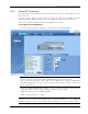
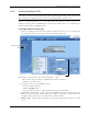

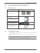


Table Of Contents
- Preface Material
- Policy for Warrantee and Repair
- General Warranty
- Specific Product Warranty Instructions
- Returns
- Limitations of Liabilities
- Reporting Defects
- Safety Warnings
- Compliance with RF Safety Requirements
- Certification and Compliance to Standards
- About This Guide
- List of Acronyms
- Table of Contents
- 1 Overview
- 2 Installation Workflow
- 3 Infrastructure Requirements and Layout Planning
- 4 VCU Unit Installation and Provisioning
- 5 VAP Installation and Provisioning
- 6 Navigating the Web Access Application
- 7 VCU Monitoring and Configuration
- 8 VAP Monitoring and Configuration
- 9 Administrative Operations
- 10 Troubleshooting
- Appendix A - Traps
- Appendix B – MobileAccess VE MIB Tree Structure (Version 1.8)

VAP Installation and Provisioning
Mixed Band LTE 700 MHz MobileAccessVE Instant Coverage Solution User Manual 37
5 VAP Installation and Provisioning
This section provides a description of the VE Access Pods (VAPs) installation, verification, and
monitoring procedures.
5.1 VAP Installation
The VAPs installation procedure consists of connecting each VAP to the Ethernet jack in the
appropriate location to provide optimal coverage (See sections
3.4.
It is recommended to install the VAPs in places located high up so as to maximize the provided
coverage per VAP.
Note: Mounting a VAP beneath a desk or in another secluded location (e.g. office corner)
decreases the effective coverage of the VAP increasing the need for a higher number of VAPs to
cover the same area.
The VAP can be installed on any flat surface (e.g. wall, lowered ceiling) whereas the screws
must be appropriate for the type of surface.
VAP Installation Considerations
• Placing units in an open area.
• Availability of CAT-5e/6 infrastructure.
• The VAPs plug into standard (RJ-45) Ethernet connection jacks.
• If the jack being used is already connected to Ethernet switch. For more information see
3.4.2
and
4.3.
• Aesthetics of the VAP location.