
User's Manual
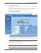
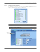
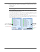
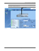
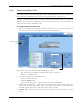


Table Of Contents
- Preface Material
- Policy for Warrantee and Repair
- General Warranty
- Specific Product Warranty Instructions
- Returns
- Limitations of Liabilities
- Reporting Defects
- Safety Warnings
- Compliance with RF Safety Requirements
- Certification and Compliance to Standards
- About This Guide
- List of Acronyms
- Table of Contents
- 1 Overview
- 2 Installation Workflow
- 3 Infrastructure Requirements and Layout Planning
- 4 VCU Unit Installation and Provisioning
- 5 VAP Installation and Provisioning
- 6 Navigating the Web Access Application
- 7 VCU Monitoring and Configuration
- 8 VAP Monitoring and Configuration
- 9 Administrative Operations
- 10 Troubleshooting
- Appendix A - Traps
- Appendix B – MobileAccess VE MIB Tree Structure (Version 1.8)

VCU Unit Installation and Provisioning
Mixed Band LTE 700 MHz MobileAccessVE Instant Coverage Solution User Manual 33
2. Mask irrelevant alarm conditions to avoid affecting the overall status of the unit. See
following example.
For Example
Note: Channel DL signal refers to the MIMO/SISO DL signal from the BS side towards the
remote units (VAPs).
In the example below “Service 2 RF DL Pwr High” alarm is masked (disabled) – this is the
alarm
for the DL signal (from the BS side)
.
The left dialog shows the alarm response when Service 2 DL RF Pwr High alarm is enabled
and a fault corresponding to that alarm is detected. (MIMO 2 DL RF Power exceeds the
defined range). The Overall Status will be RED indicating a fault.
The right side dialog shows the alarm response when Channel 2 DL RF Pwr High alarm is
masked (disabled). The Service 2 DL RF Pwr High LED will appear RED; but, the Overall
Status will be GREEN – showing NO Fault.
Figure 4-4. Unmasked Alarm (Enabled) Figure 4-5. Masked Alarm (Disabled)
Service2 RF
DL Pwr High
alarm masked
(disabled)
Service2 RF DL Pwr
High
alarm unmasked
(enabled)
Overall status
GREEN
Overall status RED