
User's Manual
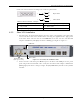
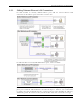
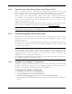
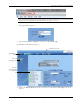

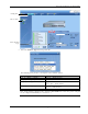
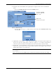
Table Of Contents
- Preface Material
- Policy for Warrantee and Repair
- General Warranty
- Specific Product Warranty Instructions
- Returns
- Limitations of Liabilities
- Reporting Defects
- Safety Warnings
- Compliance with RF Safety Requirements
- Certification and Compliance to Standards
- About This Guide
- List of Acronyms
- Table of Contents
- 1 Overview
- 2 Installation Workflow
- 3 Infrastructure Requirements and Layout Planning
- 4 VCU Unit Installation and Provisioning
- 5 VAP Installation and Provisioning
- 6 Navigating the Web Access Application
- 7 VCU Monitoring and Configuration
- 8 VAP Monitoring and Configuration
- 9 Administrative Operations
- 10 Troubleshooting
- Appendix A - Traps
- Appendix B – MobileAccess VE MIB Tree Structure (Version 1.8)

VCU Unit Installation and Provisioning
Mixed Band LTE 700 MHz MobileAccessVE Instant Coverage Solution User Manual 30
10. Assign the unit an identifiable name (optional). To assign the Master VCU an identifiable
name:
• Select the Module Info Tab and click the Modify button.
Figure 4-3. Module Info Tab
• Type the unit name (up to 17 alpha-numeric characters) in the Controller Name dialog
and click OK.
11. Uplink Cable Compensation – enable this parameter ONLY if the bonded cable lengths vary
between the VCU and VAPs (reduces noise). See Figure
4-3. It is NOT recommended to
enable this option for similar cable lengths between the VCU and the connected VAPs.
12. All Antennas – used to globally set usage of either external or internal antennas of VAPs that
support both internal and external antenna options. (Antennas that support only external or
only internal antennas are not affected.)
Note 1: The antenna type can be individually defined for each VAP via the VAP ServiceRF tab.
See section
5.5
Note 2: Internal antennas (MIMO support for Horizontal Omni-Directional Antennas Only)
Click Name
Modify
button to define the
unit a name.
Uplink Cable
Compensation option