
User's Manual
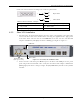
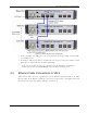
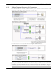
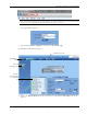

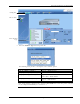
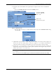
Table Of Contents
- Preface Material
- Policy for Warrantee and Repair
- General Warranty
- Specific Product Warranty Instructions
- Returns
- Limitations of Liabilities
- Reporting Defects
- Safety Warnings
- Compliance with RF Safety Requirements
- Certification and Compliance to Standards
- About This Guide
- List of Acronyms
- Table of Contents
- 1 Overview
- 2 Installation Workflow
- 3 Infrastructure Requirements and Layout Planning
- 4 VCU Unit Installation and Provisioning
- 5 VAP Installation and Provisioning
- 6 Navigating the Web Access Application
- 7 VCU Monitoring and Configuration
- 8 VAP Monitoring and Configuration
- 9 Administrative Operations
- 10 Troubleshooting
- Appendix A - Traps
- Appendix B – MobileAccess VE MIB Tree Structure (Version 1.8)

VCU Unit Installation and Provisioning
Mixed Band LTE 700 MHz MobileAccessVE Instant Coverage Solution User Manual 22
Figure 4-2. Master and Slave VCU Connections
3. Connect the Slave VCU VAP ports to the patch-panel that feeds the existing structured CAT-
5e/6 cabling system.
4. According to VAPs layout plan (as explained in section
3.4.2) connect the Ethernet switch
cables (See section
4.3 for more detailed explanation).
• If the requested jack is already in use, disconnect it from the Ethernet switch and re-
connect it to the corresponding Ethernet port in the Slave VCU front panel.
4.3 Ethernet Cable Connections to VAPs
This section describes the how to perform the relevant Ethernet LAN connections to the VAPs
from the VCUs via the Ethernet switch (See section
4.3.1) and provides a description of the PoE
transferred between the VCU and the VAPs (See section
4.3.2).