
User's Manual
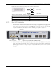
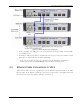
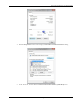

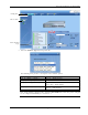
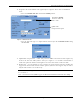
Table Of Contents
- Preface Material
- Policy for Warrantee and Repair
- General Warranty
- Specific Product Warranty Instructions
- Returns
- Limitations of Liabilities
- Reporting Defects
- Safety Warnings
- Compliance with RF Safety Requirements
- Certification and Compliance to Standards
- About This Guide
- List of Acronyms
- Table of Contents
- 1 Overview
- 2 Installation Workflow
- 3 Infrastructure Requirements and Layout Planning
- 4 VCU Unit Installation and Provisioning
- 5 VAP Installation and Provisioning
- 6 Navigating the Web Access Application
- 7 VCU Monitoring and Configuration
- 8 VAP Monitoring and Configuration
- 9 Administrative Operations
- 10 Troubleshooting
- Appendix A - Traps
- Appendix B – MobileAccess VE MIB Tree Structure (Version 1.8)

VCU Unit Installation and Provisioning
Mixed Band LTE 700 MHz MobileAccessVE Instant Coverage Solution User Manual 21
Connect the relevant alarms according to the connector pinout below.
Table 4-2. Alarms Connector – used pins
8 – Major Error Signal (Normally closed) 7 – Minor Error Signal (Normally open)
11 – Major COM 12 – Minor COM
15 –Major Error Signal (Normally open) 13 – Minor Error Signal (Normally closed)
4.2.2 Slave VCU Installation
1. Install the Slave VE Control Unit (VCU) in the Telco closet corresponding to the floor being
covered. The Slave VCU can be installed in the rack using the supplied bracket. Apply power
to the Slave VCUs and note that the VCU PWR LED is lit. Note that the unit ACT LED
completes initialization (solid light) and shows a blinking green light. See Figure
4-1
.
Figure
4-1. VCU PWR, RF and Master LEDs
2. Connect the Slave VCU front panel Master port to the Master VCU VAP port via the patch
panel using dedicated STP CAT6 cables. Verify that the Master LED completes initialization
(blinking light) and shows a solid green light. The (RF) MIMO LEDs (of both services) should
turn OFF.
1
1
8
Major Alarm
1
7
1
Minor Alarm
PWR LED
Master LED
RF Source LEDs
(One per service)