
User's Manual
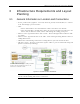
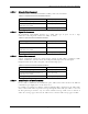
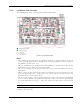

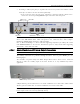
Table Of Contents
- Preface Material
- Policy for Warrantee and Repair
- General Warranty
- Specific Product Warranty Instructions
- Returns
- Limitations of Liabilities
- Reporting Defects
- Safety Warnings
- Compliance with RF Safety Requirements
- Certification and Compliance to Standards
- About This Guide
- List of Acronyms
- Table of Contents
- 1 Overview
- 2 Installation Workflow
- 3 Infrastructure Requirements and Layout Planning
- 4 VCU Unit Installation and Provisioning
- 5 VAP Installation and Provisioning
- 6 Navigating the Web Access Application
- 7 VCU Monitoring and Configuration
- 8 VAP Monitoring and Configuration
- 9 Administrative Operations
- 10 Troubleshooting
- Appendix A - Traps
- Appendix B – MobileAccess VE MIB Tree Structure (Version 1.8)

VCU Unit Installation and Provisioning
Mixed Band LTE 700 MHz MobileAccessVE Instant Coverage Solution User Manual 20
7. According to VAPs layout plan (as explained in section 3.4.2) connect the Ethernet switch
cables (See section
4.3 for more detailed explanation).
• If the requested jack is already in use, disconnect it from the Ethernet switch and re-
connect it to the corresponding Ethernet port in the Slave VCU front panel.
Note 1: After the Slave VCUs are connected (according to section
4.2.2), verify that that the
Master VCU VAP Status LEDs which correspond to the connected Slave VCUs complete
initialization (blinking light) and show a solid green light.
Note 2: When functioning as a Master VCU and supporting only Slaves (no VAPs), the control
units’ Ethernet Ports are not relevant. The Ethernet ports are only relevant when supporting
mixed mode – Slave VCUs and VAPs
4.2.1.1
Master/Stand-Alone VCU Alarm Output Connections
Note: For Master/Slave VCU configuration, the Alarms are relevant only for the Master VCU.
The auxiliary connections are performed through the Master VCU rear panel Alarms port. See
following figure.
The controller can provide Major and Minor Output Alarms. These alarms can be connected
directly to either the auxiliary input of the Base Station or to any additional dry-contact
application.
A Major Alarm is generated when there is an alarm condition in one or more VCUs, while a Minor
Alarm is generated when there is an alarm condition in one or more of the VAPs.
Note: If only one alarm is required (Minor or Major) an external connection of a wire jumper
between pins 8 and 13 is necessary (Normally closed).
RF ports
VAP Ports 1-4; 5-8; 7-12
ACT LED
VAP Status
LEDs (1-12)
Alarms port for
auxiliary connections