
User's Manual
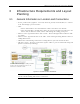
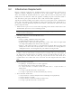
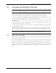
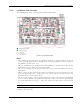
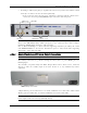
Table Of Contents
- Preface Material
- Policy for Warrantee and Repair
- General Warranty
- Specific Product Warranty Instructions
- Returns
- Limitations of Liabilities
- Reporting Defects
- Safety Warnings
- Compliance with RF Safety Requirements
- Certification and Compliance to Standards
- About This Guide
- List of Acronyms
- Table of Contents
- 1 Overview
- 2 Installation Workflow
- 3 Infrastructure Requirements and Layout Planning
- 4 VCU Unit Installation and Provisioning
- 5 VAP Installation and Provisioning
- 6 Navigating the Web Access Application
- 7 VCU Monitoring and Configuration
- 8 VAP Monitoring and Configuration
- 9 Administrative Operations
- 10 Troubleshooting
- Appendix A - Traps
- Appendix B – MobileAccess VE MIB Tree Structure (Version 1.8)

VCU Unit Installation and Provisioning
Mixed Band LTE 700 MHz MobileAccessVE Instant Coverage Solution User Manual 19
4.2 VCU Physical Installation
This section describes the physical installation and connections of the Master VCU, Slave VCUs
and the VAP Ethernet connections to the relevant VCUs.
4.2.1 Master VCU Installation
The VE Control Unit can be installed as a Master VCU and control up to (12) Slave VCUs and
VAPs and is installed in the main IDF/Telco closet. This section describes the Master VCU
installation procedures.
Note: When Master VCU only supports Slave VCUs (no VAPs), the control units’ Ethernet Ports
are not relevant and are not in use.
1. Install the Master VCU in the main Telco closet. The Master VCU can be installed in a 19”
rack, placed on a shelf, or secured using the supplied bracket.
2. Apply power to the Master VCU and verify that the PWR LED is lit. Also verify that the unit
ACT LED completes initialization (blinking light) and shows a solid green light.
3. Connect (or request the service provider’s service personnel to connect) the provider’s LTE
signal source(s) to the Master VCU front panel UL/DL simplex or DUP RF ports
(through passive interface).
4. Power on the signal sources.
Note: The RF Source LED (See following figure) of the connected port on the Master VCU
should be lit GREEN, indicating that the Master VCU senses the RF signal from the source at
the expected level (according to Max Expected Pin). After connecting the capacity source, if
the LED remains RED verify that the Max Expected Pin is configured properly and service is
enabled.
5. To connect VCU Slaves to the Master VCU: connect the Master VCU VAP ports to the
Slave VCUs Master ports via the patch-panel that feeds the dedicated STP CAT-6/7 cabling
system.
6. To connect Auxiliary alarms (connector located on the controller rear panel), refer to section
4.2.1.1