
User's Manual
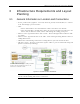
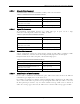
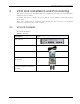
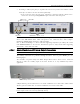
Table Of Contents
- Preface Material
- Policy for Warrantee and Repair
- General Warranty
- Specific Product Warranty Instructions
- Returns
- Limitations of Liabilities
- Reporting Defects
- Safety Warnings
- Compliance with RF Safety Requirements
- Certification and Compliance to Standards
- About This Guide
- List of Acronyms
- Table of Contents
- 1 Overview
- 2 Installation Workflow
- 3 Infrastructure Requirements and Layout Planning
- 4 VCU Unit Installation and Provisioning
- 5 VAP Installation and Provisioning
- 6 Navigating the Web Access Application
- 7 VCU Monitoring and Configuration
- 8 VAP Monitoring and Configuration
- 9 Administrative Operations
- 10 Troubleshooting
- Appendix A - Traps
- Appendix B – MobileAccess VE MIB Tree Structure (Version 1.8)

VCU Unit Installation and Provisioning
Mixed Band LTE 700 MHz MobileAccessVE Instant Coverage Solution User Manual 18
4 VCU Unit Installation and Provisioning
This chapter describes the installation and
basic configuration procedures
for VE Control Units
(VCU) located on each floor.
In addition, this chapter describes the how to shift the relevant Ethernet connections required
for the VAPs.
These steps should only be performed after planning the floor coverage and installation
locations, as described in the previous sections.
4.1 VCU Kit Contents
The VE VCU Kit includes:
Table
4-1: VCU Kit
Description Unit
VE LTE 700 MHz MIMO Control
Unit (VCU) Kit
Power Cord
VE SW CD
Local Configuration Cable (crossed
RJ-45 cable)
Brackets Used to secure the VCU to
a 19” rack (shipped assembled to
the VCU)