
User's Manual
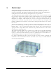
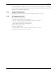
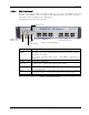
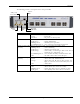
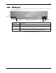
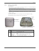
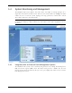
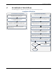
Table Of Contents
- Preface Material
- Policy for Warrantee and Repair
- General Warranty
- Specific Product Warranty Instructions
- Returns
- Limitations of Liabilities
- Reporting Defects
- Safety Warnings
- Compliance with RF Safety Requirements
- Certification and Compliance to Standards
- About This Guide
- List of Acronyms
- Table of Contents
- 1 Overview
- 2 Installation Workflow
- 3 Infrastructure Requirements and Layout Planning
- 4 VCU Unit Installation and Provisioning
- 5 VAP Installation and Provisioning
- 6 Navigating the Web Access Application
- 7 VCU Monitoring and Configuration
- 8 VAP Monitoring and Configuration
- 9 Administrative Operations
- 10 Troubleshooting
- Appendix A - Traps
- Appendix B – MobileAccess VE MIB Tree Structure (Version 1.8)

Installation Workflow
Mixed Band LTE 700 MHz MobileAccessVE Instant Coverage Solution User Manual 10
2 Installation Workflow
The following figure summarizes the main steps of the installation procedure:
Verify that all infrastructure requirements are met (includes
verifying that the jacks are wired to the patch panel in the
communication rooms).
Check that Ethernet jacks are available
in all planned VAP locations.
Plan the floor coverage and VAP locations
according to the type/density of the site.
Installation Workflow
Determine the communication rooms to which the VAP
infrastructure is connected (locations for the Slave VCUs).
Install the Master VCU in the IDF/telco shaft.
Complete
Open a local session to the Master VCU and configure the system
parameters (IP, and service parameters: Central Frequency , Max
expected Pin).
Perform a “walk test” and verify coverage around the floor.
Change VAPs locations or
add VAPs
Met
Coverage?
No
Install the Slave VCUs and connect them to the Master VCU (verify
that the VCU/VCH LED is green, and RF LEDs turned OFF).
Install the VAPs and connect them to the Ethernet jacks. Connect
the Ethernet appliance (if exists) to the VAP. Check that the VAP is
operational (Blue LED lit). Check that Ethernet connection is OK.
Yes
Install the RF signal sources, connect them to the master VCU
(through passive interfaces) and check that the RF signals are
received by the VCU (i.e. that the RF LEDs are green).
Connect the VCU
VAP
ports to the patch panel, and
the Ethernet Switch to the VCU
Ethernet
ports.
1. Infrastructure Preparation
2. Installation Procedure