
User's Manual
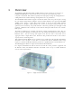
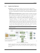
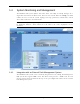
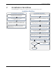
Table Of Contents
- Preface Material
- Policy for Warrantee and Repair
- General Warranty
- Specific Product Warranty Instructions
- Returns
- Limitations of Liabilities
- Reporting Defects
- Safety Warnings
- Compliance with RF Safety Requirements
- Certification and Compliance to Standards
- About This Guide
- List of Acronyms
- Table of Contents
- 1 Overview
- 2 Installation Workflow
- 3 Infrastructure Requirements and Layout Planning
- 4 VCU Unit Installation and Provisioning
- 5 VAP Installation and Provisioning
- 6 Navigating the Web Access Application
- 7 VCU Monitoring and Configuration
- 8 VAP Monitoring and Configuration
- 9 Administrative Operations
- 10 Troubleshooting
- Appendix A - Traps
- Appendix B – MobileAccess VE MIB Tree Structure (Version 1.8)

Overview
Mixed Band LTE 700 MHz MobileAccessVE Instant Coverage Solution User Manual 9
1.4 System Monitoring and Management
The MobileAccessVE system (Master VCU, Slave VCUs, and VAPs) is centrally managed via a
single Web connection to the Master VCU. The basic screen in the GUI is the Config tab, which
enables the user to view the system topology and setup parameters, Control Units, and all
Access Pods connected to the Control Units.
Note: When locally connecting to a specific Slave VCU, only the VAPs connected to this VCU can
be monitored. However, when connected to the Master, the entire deployment can be
monitored.
1.4.1 Integration with an External Fault Management System
The MobileAccessVE system can be seamlessly integrated into any existing Fault Management
(FM) system that supports SNMP events. The Master VCU generates a SNMP event for each
relevant system alarm and forwards this trap to the pre-configured IP address of the external
Fault Management system.