
User's Manual
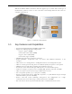
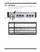
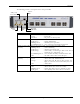
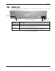
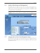
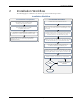
Table Of Contents
- Preface Material
- Policy for Warrantee and Repair
- General Warranty
- Specific Product Warranty Instructions
- Returns
- Limitations of Liabilities
- Reporting Defects
- Safety Warnings
- Compliance with RF Safety Requirements
- Certification and Compliance to Standards
- About This Guide
- List of Acronyms
- Table of Contents
- 1 Overview
- 2 Installation Workflow
- 3 Infrastructure Requirements and Layout Planning
- 4 VCU Unit Installation and Provisioning
- 5 VAP Installation and Provisioning
- 6 Navigating the Web Access Application
- 7 VCU Monitoring and Configuration
- 8 VAP Monitoring and Configuration
- 9 Administrative Operations
- 10 Troubleshooting
- Appendix A - Traps
- Appendix B – MobileAccess VE MIB Tree Structure (Version 1.8)

Overview
Mixed Band LTE 700 MHz MobileAccessVE Instant Coverage Solution User Manual 7
1.3.1.2
VCU Rear Panel
The rear panel includes the following: power switch, AC input, AUX alarms, and service
personnel connections.
Figure 1-5. VCU Rear Panel
Connector Description
Console RS232 local connection for service personnel (D-Type 9)
Alarms
AUX alarms connections - see section
4.2.1.1.
In Master/Slave
configuration - relevant only for Master VCU.
Power Input
Standard 3-pins AC power connector equipped with an ON/OFF switch.
90-264V AC, 47-63 Hz AC; 350W power consumption maximum.
Table 1-3: VCU Rear Panel Description
PWR On/Off
Switch
AC
Connector
AUX Alarms
Console
Connector