
User's Manual
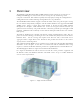
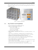
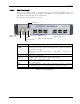
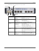
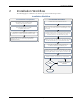
Table Of Contents
- Preface Material
- Policy for Warrantee and Repair
- General Warranty
- Specific Product Warranty Instructions
- Returns
- Limitations of Liabilities
- Reporting Defects
- Safety Warnings
- Compliance with RF Safety Requirements
- Certification and Compliance to Standards
- About This Guide
- List of Acronyms
- Table of Contents
- 1 Overview
- 2 Installation Workflow
- 3 Infrastructure Requirements and Layout Planning
- 4 VCU Unit Installation and Provisioning
- 5 VAP Installation and Provisioning
- 6 Navigating the Web Access Application
- 7 VCU Monitoring and Configuration
- 8 VAP Monitoring and Configuration
- 9 Administrative Operations
- 10 Troubleshooting
- Appendix A - Traps
- Appendix B – MobileAccess VE MIB Tree Structure (Version 1.8)

Overview
Mixed Band LTE 700 MHz MobileAccessVE Instant Coverage Solution User Manual 6
The following provides a description of the front panel LEDs.
LED
Description
PWR Indicates whether the VCU receives power:
Green - Power OK
Disabled - No power received by VCU
ACT VCU activity LED:
Solid Green – During initialization
Blinking Green – Normal system operation
Fast Blinking Green – User activated
VCU Identify
on this VCU
VAP Status (O
ne LED
per Port)
Indicates the status of the
corresponding
unit (VAP or VCU)
Blinking Green – Unit is initializing
Solid Green – Normal operation of unit
Solid Orange – Unit is faulty, or unmanaged. This can be due to
mismatch type, VoIP phone, etc.
Fast Blinking Green – User invoked “Identify” command on the unit
Off – No VAP or VCU connected to this port.
MIMO (One LED per
Channel)
Indicates the status of connected RF capacity source:
Green – Master VCU only. Normal RF level
Orange – Master VCU only. RF level is either too low, too
high, or service has been turned off by the user.
Off – VCU is Slave.
Master Indicates the status of the connection to the Master VCU:
Off – Master mode (not connected to VCU)
Blinking Green – During Attachment process with Master VCU
Solid green – Slave (IF-IF) mode and connected to Master
Table 1-2: VCU LEDs Description
PWR LED
ACT LED
VAP (1-
12)
Status LEDs
Master
LED
MIMO1
LED
MIMO2
LED