
User's Manual
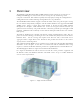
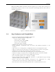
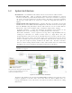
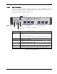
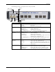
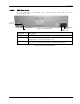
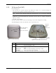
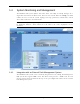
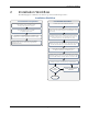
Table Of Contents
- Preface Material
- Policy for Warrantee and Repair
- General Warranty
- Specific Product Warranty Instructions
- Returns
- Limitations of Liabilities
- Reporting Defects
- Safety Warnings
- Compliance with RF Safety Requirements
- Certification and Compliance to Standards
- About This Guide
- List of Acronyms
- Table of Contents
- 1 Overview
- 2 Installation Workflow
- 3 Infrastructure Requirements and Layout Planning
- 4 VCU Unit Installation and Provisioning
- 5 VAP Installation and Provisioning
- 6 Navigating the Web Access Application
- 7 VCU Monitoring and Configuration
- 8 VAP Monitoring and Configuration
- 9 Administrative Operations
- 10 Troubleshooting
- Appendix A - Traps
- Appendix B – MobileAccess VE MIB Tree Structure (Version 1.8)

Overview
Mixed Band LTE 700 MHz MobileAccessVE Instant Coverage Solution User Manual 3
1.2 System Architecture
Main Elements - The MobileAccessVE solution is based on two elements: VAPs and VCUs:
• VE Access Pod (VAP) – VAPs are pluggable, wideband antennas distributed at strategic
locations on the floor to provide Ethernet connection to an IP device and wireless coverage of
the service via integrated internal or external antennas. The VAPs are powered by PoE from
the VCU. Up to twelve VAPs can be connected to a single VCU using LAN cables (CAT-5e or
higher).
• VE Mixed-Band LTE Control Unit (VCU) – Supports both Upper C and Lower A, B, C LTE
700MHz bands in various MIMO and SISO configurations. The VCU extends the wireless signal
from the BTS/BDA (along with PoE) to hosted VAPs connected over the standard Ethernet
infrastructure. VCUs can be installed in either a Standalone of Master/Slave topology:
Standalone installation – a single VCU installed in the IDF/Telco closet interfaces to the
BTS/BDA source, feeds and manages up to 12 VAPs (usually on the same floor).
Master/Slave installation – used to expand site coverage from a single BTS/BDA source by
enabling the connections of a number of Slave VCUs to a single Master VCU. The
(designated) Master VCU is located in the main IDF/Telco closet, interfaces with the service
provider’s RF capacity sources and provides single source management for all the hosted
elements. Each Slave VCU can host up to 12 VAPs where VAPs can also be connected to any
free ports (not occupied by Slaves) available on the Master VCU. The Master and Slave
VCUs are connected using
dedicated
CAT-6/7 cables. VCUs in Slave modes are automatically
identified by the system according to their physical connections to the Master.
Note: When the total number of VAPs in the deployment exceeds 72, consult with
MobileAccess support.
The following figure shows the Multi-tier VE LTE 700 MHz MIMO solution architecture.
Figure 1-3. VE Multi-Tier Basic Architecture
The Master VCU distributes the wireless LTE 700MHz MIMO (or SISO) services from the service
provider’s equipment to the Slave VCUs. At the Slave VCUs, the wireless MIMO services are
converged with Ethernet service and routed to the VAPs via the Ethernet LAN CAT-5e/6 cabling
infrastructure.
Note: If the Master VCU supports VAPs (in addition
to VCUs), the relevant Ethernet ports are also
connected to an Ethernet switch.