
User's Manual
Troubleshooting
LTE 700 MHz MobileAccessVE Instant Coverage Solution User Manual 69
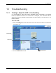
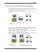
VE Connections in Central Ethernet Source Topologies
This section describes the VE site installation for sites whose Ethernet services are provided from
a single Ethernet source in the communication room and distributed throughout the site by
daisy-chaining Ethernet switches from the central source.
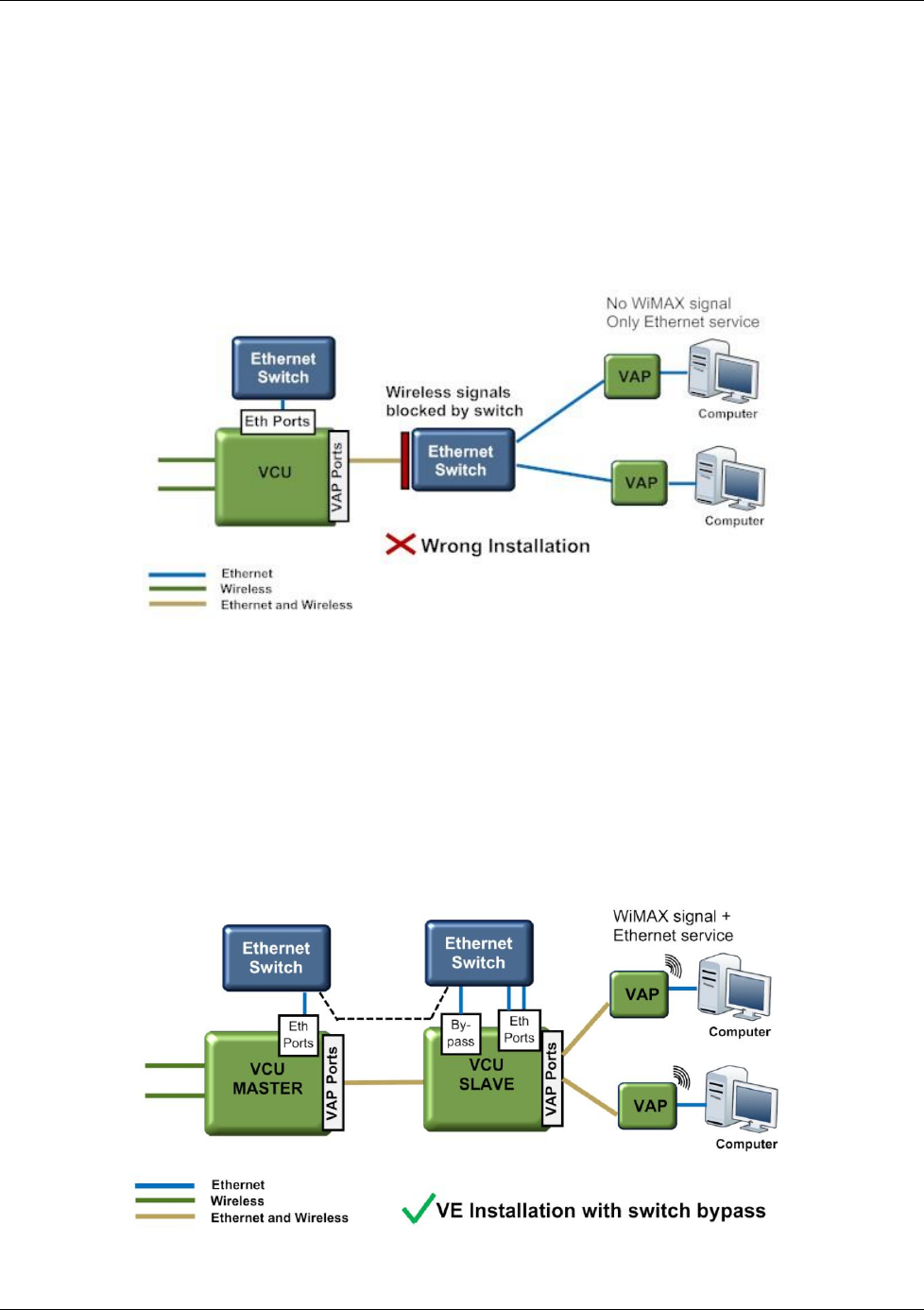
In VE installation, any switch located in the path between the VCU and the VAPs will block the
wireless signals:
The Bypass option allows bypassing the switch by enabling the transport Ethernet signals over
the cable connecting the Master VCU to the slave VCU. (In a typical VE the cable between the
Master and Slave VCUs is a dedicated CAT-6 cable used only for VE).
The Ethernet signals are combined with the wireless signals at the master VCU, separated at the
slave VCU and connected via the Bypass port to the switch.
The wireless signals are then re-combined by the slave VCU with the Ethernet signals (from the
Ethernet Switch Ports) and transported to the VAPs and connected PCs.