
User's Manual
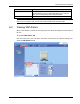

VAP Monitoring and Configuration
LTE 700 MHz MobileAccessVE Instant Coverage Solution User Manual 54
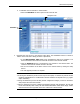
The following table provides a description of the displayed VAP RF parameters (in SISO
service mode, only Channel 1 parameters are displayed).
Parameter
Description
Type
Set according to unit type (LTE)
Channel 1/
Channel 2 Antenna
Select External only if an external antenna is connected to this VAP.
Otherwise, the option should be set to Internal (default).
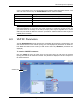
Tx Pout Level
Level of from BS side.
Normal = output power will be at required (normal) level
Low = output power will be attenuated by 5 dB less than the required level.
This option can be used for smaller coverage areas that do not require the
full power of the VAP for coverage.
Channel 1/
Channel 2 Tx Pout
Measured output power. Normal output power is approximately 14dBm.
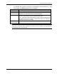
Note: VAP RF settings (Service Mode, DL Pout Level, Antenna) are saved in the VCU associated
to the port to which the VAP is connected, such that in case you replace a VAP all parameters
are automatically set to the new VAP.