
User's Manual
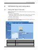
VCU Monitoring and Configuration
LTE 700 MHz MobileAccessVE Instant Coverage Solution User Manual 48
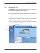
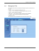
Field
Description
SW Active Version
Version of the SW currently being used to manage and monitor
the system
SW Inactive Version
Version of other system SW version not in use
Identify Button
Enabling this option enables finding the physical location of the
selected element (see 10.1). When this option is set to ON, the
LEDs on the corresponding VAP/VCU flickers.
Reset Button
SW reset of the unit
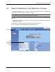
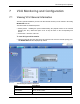
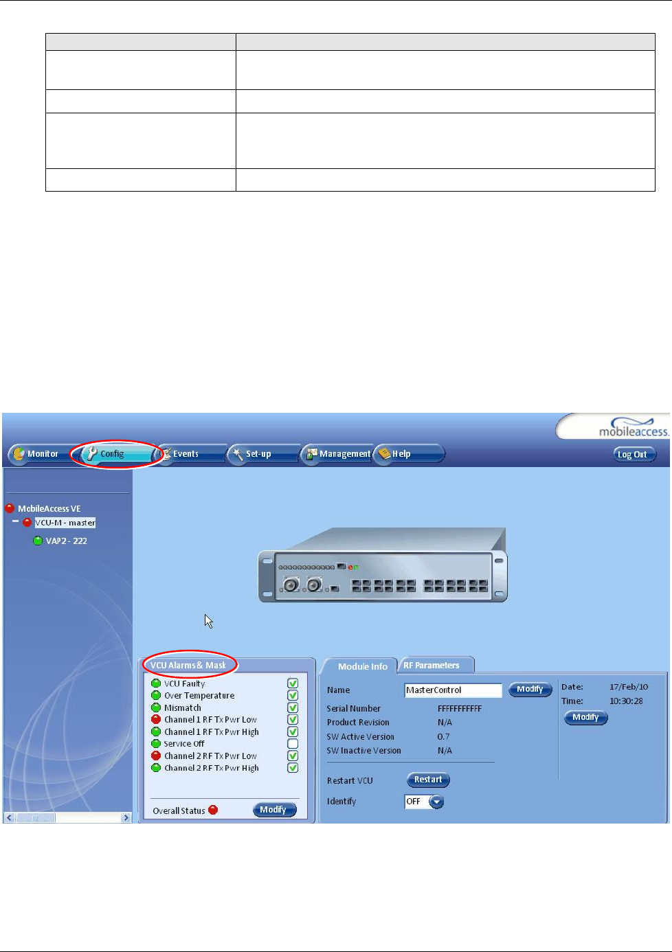
7.2 Viewing VCU Alarms
The alarms displayed in the Alarms tab correspond to the VCU (Master/Slave) selected in the
topology tree. When a VCU element is selected in the topology tree, the Alarm tab displays the
main alarms in the unit.
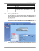
To view VCU Alarms
In the Topology Tree select the Control Unit (VCU) then click the Config(uration) tab in the
menu bar located at the top of the window. Refer to the VCU Alarms and Mask sub tab.
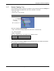
If one or more alarms occur, the corresponding Status indicator will be illuminated in RED. If the
VCU is OK and no fault occurs, the Overall Status indicator will show GREEN.