
User's Manual
VCU Unit Installation and Provisioning
LTE 700 MHz MobileAccessVE Instant Coverage Solution User Manual 32
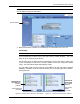
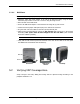
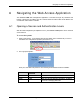
Note: To briefly check the VCU status, click on the VCU name in the Topology Tree. The VCU
icon will appear, showing the LEDs status.
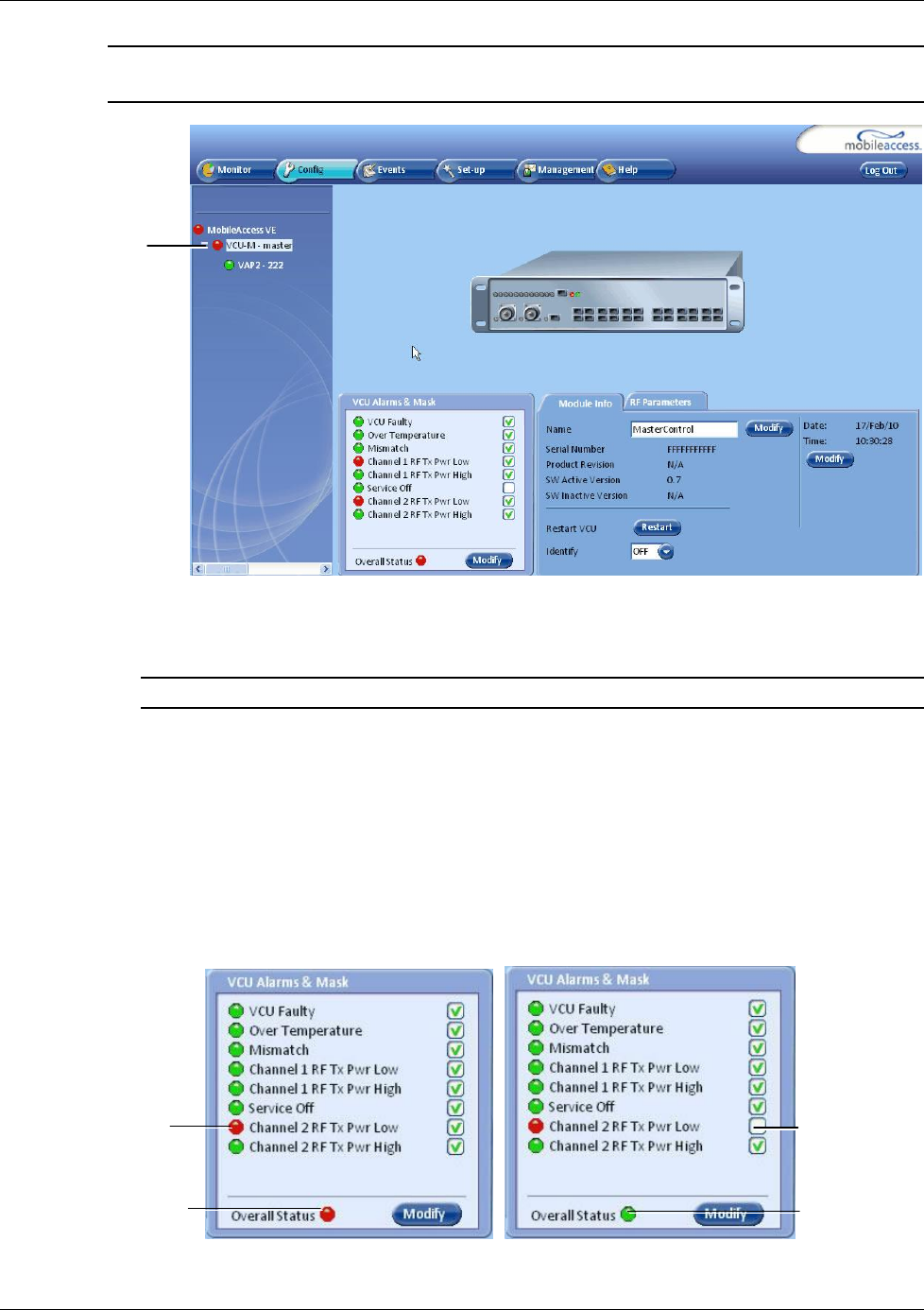
2. Mask irrelevant alarm conditions to avoid affecting the overall status of the unit. See
For Example
NOTE: Tx signal refers to the DL signal from the BS side towards the remote units (VAPs).
In the example below “Channel 2 RF Tx Pwr High” alarm is masked (disabled) – this is the
alarm
for the DL signal (from the BS side)
.
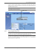
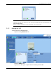
The left dialog shows the alarm response when MIMO2 Tx RF Pwr High alarm is enabled and
a fault corresponding to that alarm is detected. (MIMO2 Tx RF Power exceeds the defined
range). The Overall Status will be RED indicating a fault.
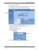
The right dialog shows the alarm response when MIMO2 Tx RF Pwr High alarm is disabled
(MASKED). The MIMO2 Tx RF Pwr High LED be RED; but, the Overall Status will be GREEN –
showing NO Fault.
Figure 4-3. Service2 Service Off Alarm – Not Masked Figure 4-4. . Service2 Service Off Alarm –Masked
Channel2 RF
Tx Pwr High
alarm masked
(disabled)
Channel2 RF Tx
Pwr High alarm
unmasked
(enabled)
Overall status RED
- accordingly
Click VCU Master
Overall status
GREEN-
accordingly