
User's Manual
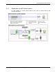
VCU Unit Installation and Provisioning
LTE 700 MHz MobileAccessVE Instant Coverage Solution User Manual 30
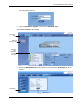
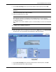
2. Click the DL CF Modify button. Enter the Base Station central frequency and click OK.
Note: The MIMO DL CF parameter defines the same DL central frequency for Channel 1 and
Channel 2.
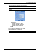
3. Define Max expected power of BTS (0-33dBm).
4. Define Rx System Gain (-15 to 5dB)
Notes:
Max expected Pin and DL CF parameters can be obtained from your service provider.
The remaining parameters are predefined to their default values. (Service Bandwidth is set
to 10MHz per channel).
Any updates of the service definition (DL CF or Service Mode) are sent to all connected
VAPs.
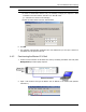
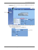
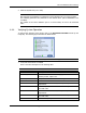
To configure the SISO RF parameters:
Note: The RF tab is displayed for MIMO by default.
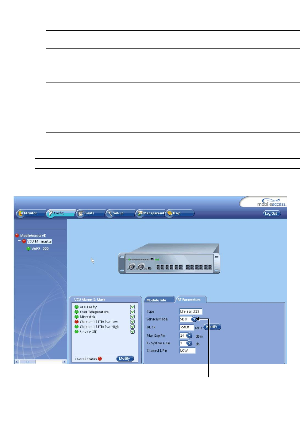
1. Select the Master VCU in the topology tree and select the SISO option in the Service Mode
drop-down list. The RF parameters tab will display the SISO RF parameters.
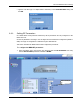
2. Click the DL CF Modify button and enter the Base Station central frequency. Click OK.
3. Define Max expected power of BTS (0-33dBm).
Service Mode
drop-down list