
User's Manual

VCU Unit Installation and Provisioning
LTE 700 MHz MobileAccessVE Instant Coverage Solution User Manual 20
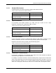
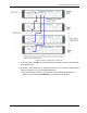
Note: If only one alarm is required (Minor or Major) an external connection of a wire jumper
between pins 8 and 13 is necessary (normally closed).
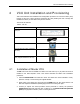
Connect the relevant alarms according to the connector pinout below.
Table 9. Alarms Connector – used pins
8 – Major Error Signal (normally closed)
7 – Minor Error Signal (normally open)
11 – Major COM
12 – Minor COM
15 –Major Error Signal (normally open)
13 – Minor Error Signal (normally closed)
4.3 Installation of Slave VCU
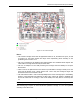
1. Install the Slave VE Control Unit (VCU) in the Telco closet corresponding to the floor being
covered. The Slave VCU can be installed in the rack using the supplied bracket in the IDF closet. Apply
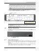
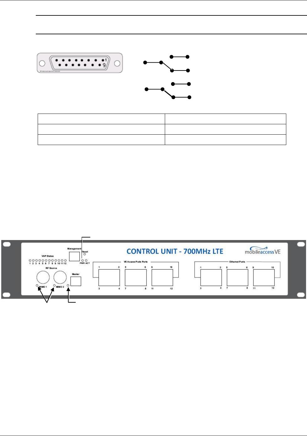
power to the Slave VCUs and note that the VCU PWR LED is lit. Note that the unit ACT LED completes
initialization (solid light) and shows a blinking green light. See
Figure 4-1
.
Figure 4-1. VCU PWR, RF and Master LEDs
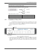
2. Connect the Slave VCU front panel Master port to the Master VCU VAP port via the patch
panel using dedicated CAT6 cables. Verify that the Master LED completes initialization
(blinking light) and shows a solid green light. The (RF) MIMO LEDs (of both services) should
turn OFF.
11
15
8
Major Alarm
12
7
13
Minor Alarm
PWR LED
Master LED
RF Source LEDs
(one per service)