
User's Manual

Infrastructure Requirements and Layout Planning
LTE 700 MHz MobileAccessVE Instant Coverage Solution User Manual 11
3 Infrastructure Requirements and Layout
Planning
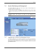
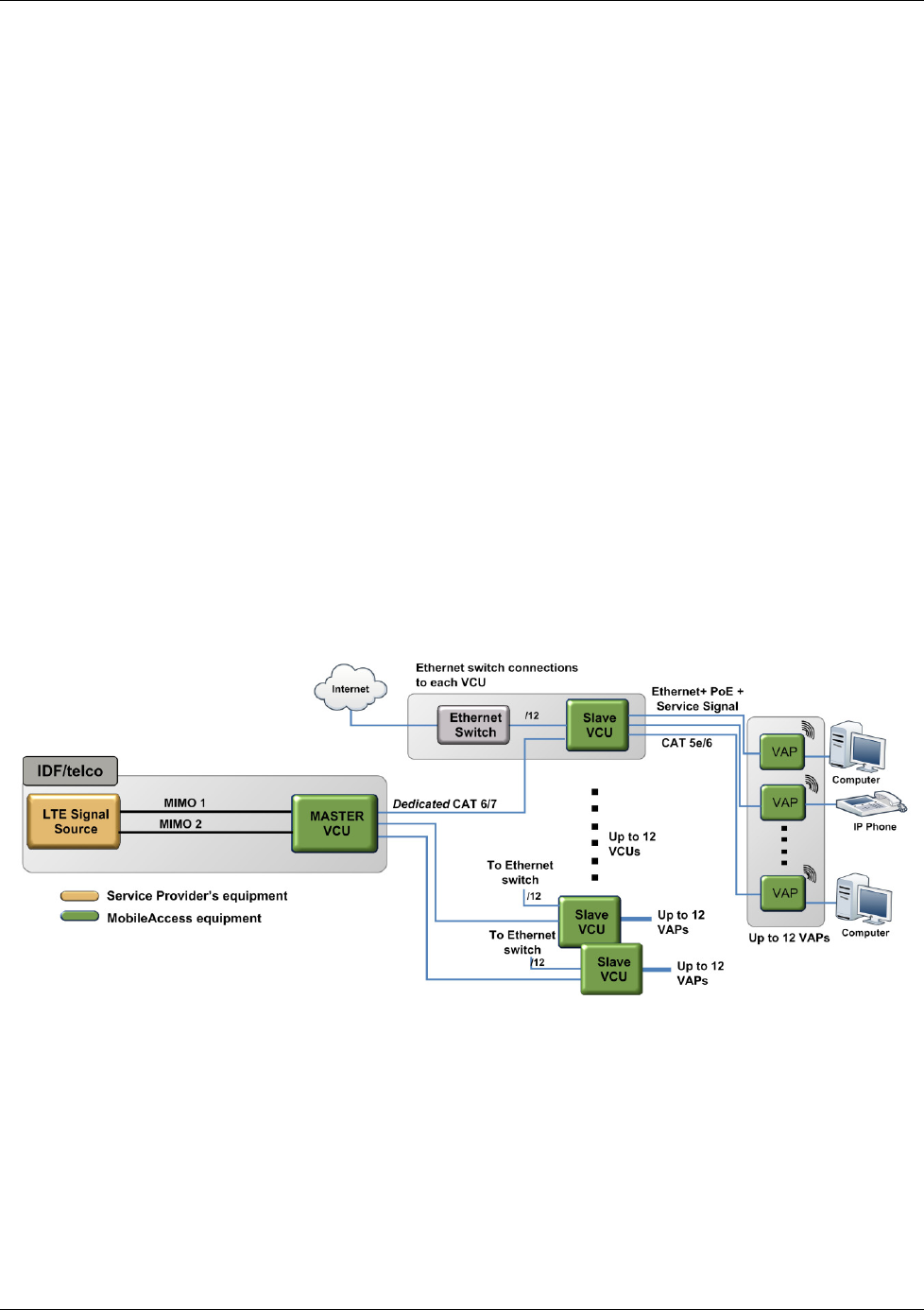
3.1 General Information on Location and Connections
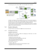
Service provider’s RF equipment - Macrocell, Microcell, Picocell, Femtocell, BDA, etc.
connects to the VCU through a passive interface.
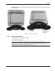
VCUs:
Master VCU installed at the main IDF/telco cabinet and connected to all VCUs.
Slave VCUs installed at the IDF/telco cabinet of each covered floor and connected to
the Master VCU, the Ethernet switch, and the VAPs through the cabling patch panel.
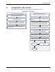
Wireless service signals from Master VCU to VCUs – routed through dedicated Ethernet
CAT-6/7 cabling.
Wireless service signals from VCUs to the VAPs – routed through existing Ethernet CAT-
5e/6 cabling infrastructure.
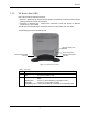
VAP location and mounting – wall mounting or desk mounting. Connection to existing
Ethernet jack (and external antenna if required).
VAP power source - No power connections required. VAPs are power fed from VCU using
PoE (Power over Ethernet) technology.
Figure 3-1. VE Multi-Tier Basic Architecture