
User's Manual

Overview
LTE 700 MHz MobileAccessVE Instant Coverage Solution User Manual 4
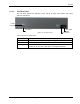
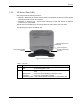
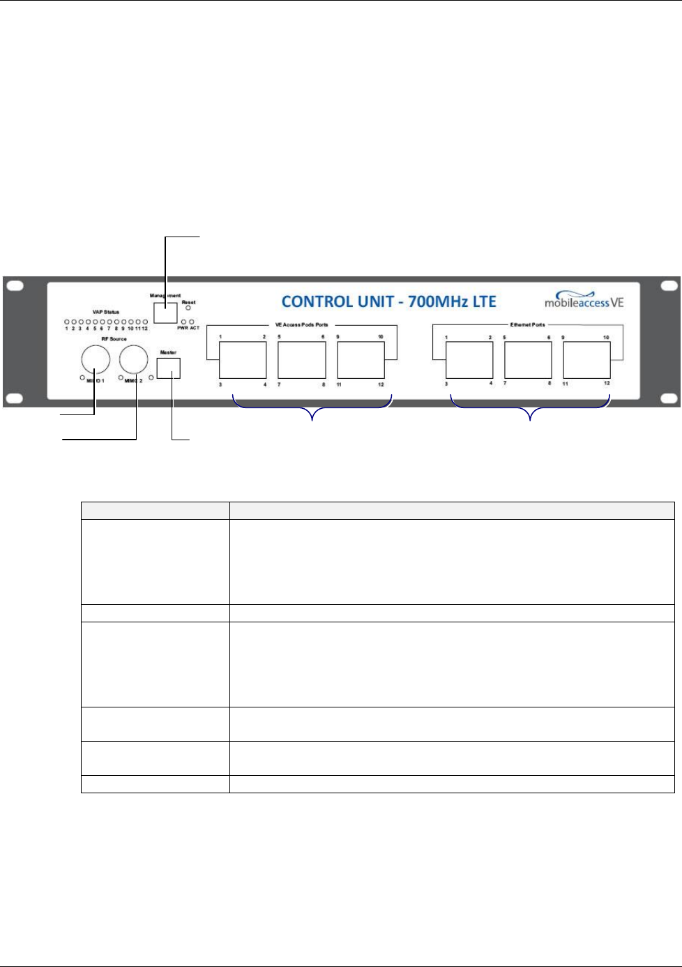
1.2.1.1 VCU Front Panel
The front panel supports the interfaces to the wireless LTE MIMO service (two channels –
corresponding to the two supported TDD MIMO channels) and includes interfaces to VAPs or
Slave VCUs (depending on the configuration).
The front panel also interfaces to the Ethernet switch, includes a connector (Master) for
receiving the wireless LTE MIMO services from the Master VCU (in Master/Slave configuration)
and the management interface.
The following provides the front panel ports.
Figure 1-4. VCU Front Panel
Table 1: VCU Ports Description
Ports
Description
MIMO1
MIMO2
RF connections (two TDD MIMO channels) to the service provider
LTE Signal Source equipment. N-Type female connectors. Coax
cables.
Note: When supporting SISO service – only MIMO 1 connector is
relevant.
Management
RJ45 WEB management connection.
VE Access Pod Ports
1-4; 5-8; 7-12
VAP/VCU port connections. RJ-45 connection to VAP/VCU through the
LAN infrastructure. CAT-5e/6 cables.
If VCU is connected as Master – these are connections to the Slave
VCUs.
If VCU is connected as Slave – these are connections to VAPs.
Ethernet Ports 1-4;
5-8; 7-12
Ethernet port connections to Ethernet Switch. Ethernet cables (used
only in Slave VCUs).
Master
Used for connecting a Slave VCU to the Master VCU in a multi-tier
deployment (connects to one of the VAP ports of the Master VCU).
Reset
N/A in current version.
Ethernet Ports 1-4; 5-8; 7-12
VAP Ports 1-4; 5-8; 7-12
Management
MIMO 2
MIMO 1
Master
Port