MobileAccessVE LTE 700 MHz MIMO Instant Coverage Solution User Manual P/N: 709C006201 REV: A00 Date: APRIL 2010
Preface Material MobileAccess Worldwide Headquarters 8391 Old Courthouse Road Suite 300, Vienna, VA 22182 Tel: +1(866)436-9266, +1(703)848-0200 TAC: +1(800)787-1266, Fax: +1(703)848-0280 http://www.MobileAccess.
Preface Material Preface Material © Copyright 2010, MobileAccess Networks Inc. All Rights Reserved. This document contains confidential and proprietary information of MobileAccess and may not be copied, transmitted, stored in a retrieval system or reproduced in any format or media, in whole or in part, without the prior written consent of MobileAccess.
Preface Material Returns In the event that it is necessary to return any product against above warranty, the following procedure shall be followed: 1. Return authorization is to be received from MobileAccess prior to returning any unit. Advise MobileAccess of the model, serial number, and discrepancy. The unit may then be forwarded to MobileAccess, transportation prepaid. Devices returned collect or without authorization may not be accepted. 2.
Preface Material Certification and Compliance to Standards Category Standards Safety: IEC 60950-1: 2003; UL-60950-1:2003; CAN/CSA – C22.2 No 60950-1-03 EMC: 47CFR 15.
Preface Material About This Guide This guide provides essential product functionality with all the information necessary for proper installation and configuration of the MobileAccessVE system.
Table of Contents 1 Overview .............................................................................................................................1 1.1 System Architecture ..................................................................................................................... 2 1.2 System Elements ......................................................................................................................... 3 1.2.1 VE Control Unit (VCU) ......................................
Table of Contents 4.4 Provisioning the VE Control Unit.................................................................................................. 24 4.4.1 Configure the Computer IP Parameters .............................................................................. 24 4.4.2 Provisioning the Master VCU Unit ...................................................................................... 25 4.4.3 Setting RF Parameters .........................................................................
Table of Contents 9 Administrative Operations...............................................................................................55 9.1 Changing Password .................................................................................................................... 55 9.2 IP Settings ................................................................................................................................ 56 9.3 SNMP Configuration Parameters ..........................................
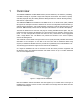
1 Overview The MobileAccessVE LTE 700 MHz MIMO solution provides enhanced, cost effective, in-building LTE MIMO coverage for any small to large-sized enterprise environment. This solution is quickly and easily deployed using the existing Ethernet cabling infrastructure without affecting existing LAN services or performance.
Overview Figure 1-2. Multi-Tier VE Installation 1.1 System Architecture Main Elements - The MobileAccessVE solution is based on the following main elements: VE Control Unit (VCU) – The control Unit can serve as either a Master or a Slave and interfaces the other VCUs (in case of Master) or the VAPs (when serving as Slave). The Master or Slave mode is automatically detected according to the VCU's physical connection.
Overview The following figure shows the Multi-tier VE LTE 700 MHz MIMO solution architecture. Figure 1-3. VE Multi-Tier Basic Architecture The Master VCU distributes the wireless MIMO services from the service provider’s equipment to the Slave VCUs. At the Slave VCUs, the wireless MIMO services are converged with Ethernet service and routed to the VAPs via the Ethernet LAN CAT-5e/6 cabling infrastructure.
Overview 1.2.1.1 VCU Front Panel The front panel supports the interfaces to the wireless LTE MIMO service (two channels – corresponding to the two supported TDD MIMO channels) and includes interfaces to VAPs or Slave VCUs (depending on the configuration). The front panel also interfaces to the Ethernet switch, includes a connector (Master) for receiving the wireless LTE MIMO services from the Master VCU (in Master/Slave configuration) and the management interface.
Overview The following provides a description of the front panel LEDs.
Overview 1.2.1.2 VCU Rear Panel The rear panel includes the following: power switch, AC input, AUX alarms, and service personnel connections. Console connector AUX Alarms Figure 1-5. VCU Rear Panel PWR On/Off switch AC connector Table 3: VCU Rear Panel Description Connector Description Console RS232 local connection for service personnel (D-Type 9) Alarms AUX alarms connections - see section 4.2 Power Input Standard 3-pins AC power connector equipped with an ON/OFF switch.
Overview 1.2.2 VE Access Pod (VAP) Each VAP provides the following functions: Antennas – distributes the wireless services signals. The antennas are internal, where external (optional) antennas can also be connected. Connection to Ethernet port – relevant when connected to jacks that provide an Ethernet connection to a user terminal. The VAP can be mounted/hung on the wall or placed on a flat surface (such as a desk). The following figure shows the desktop VAP.
Overview The following figure shows the desktop VAP rear side and the underside view with the CAT-5e/6 patch-cord cable. RJ-45 Connector to VCU Figure 1-7. VE Access Pod-Rear 1.2.2.1 RJ-45 Connector to LAN terminal (e.g. computer) VAP Antenna Options Two antenna options are available for VAPs: Integral internal antennas Connectors that interfaces to external antennas for special coverage requirements. Note: By default, the VAP is set to transmit through the integrated internal antennas.
Overview 1.3 System Monitoring and Management The MobileAccessVE system (Master VCU, Slave VCUs, and VAPs) is centrally managed via a single Web connection to the Master VCU. The basic screen in the GUI is the Config tab, which enables the user to view the system topology and setup parameters, Control Units, and all Access Pods connected to the Control Units. Note: When locally connecting to a specific Slave VCU, only the VAPs connected to this VCU can be monitored.
Installation Workflow 2 Installation Workflow The following figure summarizes the main steps of the installation procedure: Installation Workflow 1. Infrastructure Preparation 2. Installation Procedure Plan the floor coverage and VAP locations according to the type/density of the site. Install the Master VCU in the IDF/telco shaft. Check that Ethernet jacks are available in all planned VAP locations.
Infrastructure Requirements and Layout Planning 3 Infrastructure Requirements and Layout Planning 3.1 General Information on Location and Connections Service provider’s RF equipment - Macrocell, Microcell, Picocell, Femtocell, BDA, etc. connects to the VCU through a passive interface. VCUs: Master VCU installed at the main IDF/telco cabinet and connected to all VCUs.
Infrastructure Requirements and Layout Planning 3.2 Infrastructure Requirements Ethernet standards specify that the maximum distance between an Ethernet switch and an appliance (computer, WLAN AP etc) should not exceed 100m (300ft).
Infrastructure Requirements and Layout Planning 3.3 Coverage and Installation Planning Note: The following section provides information required for planning the VAP installation on a single floor. In a multi-tier installation, this procedure is performed for each individual floor. The maximal coverage area of each VAP is affected by the density and type of environment being covered.
Infrastructure Requirements and Layout Planning 3.3.1.1 Standard Environment A traditional office environment with offices, hallways and scattered cubicles. Table 5: Standard Environment Installation Distances 3.3.1.2 Signal Propagation from VAP 56 feet (19 m) Recommended Spacing between VAPs 112 feet (38 m) Recommended Maximum distance of VAPs from outer walls 56 feet (19 m) Coverage area per VAP 9,900 sqft (920 sqm) Open Environment An environment with minimal obstacles (e.g. walls).
Infrastructure Requirements and Layout Planning 3.4 Planning VAP Layout The following section describes the steps of planning VAPs along the covered floor. At the end of this section an example of a planning map is provided. Note: It is highly recommended to use a floor plan when planning the VAPs locations. 3.4.
Infrastructure Requirements and Layout Planning Figure 3-2. Floor Plan Example Notes: The red VAP coverage circles have an approximate radius of 41, 56 and 64 foot (13.5, 19 and 21 meters) for the small, medium and large circles respectively (drew according to the guidelines given in section 3.3.1. VAP 3 is surrounded by the bathroom and stairwell which are considered dense objects and would reduce coverage in that area by the other VAPs.
Infrastructure Requirements and Layout Planning Figure 3-3. Distributed VAPs propagation, 12dBm output power @ 1.
VCU Unit Installation and Provisioning 4 VCU Unit Installation and Provisioning This section describes the installation and configuration procedures for VE Control Units (VCU) located on each floor. These should be performed only after planning the floor coverage and installation locations, as described in the previous sections.
VCU Unit Installation and Provisioning Note: The RF Source LED (see following figure) of the connected port on the Master VCU should be lit GREEN, indicating that the Master VCU senses the RF signal from the source at the expected level (according to Max Expected Pin). After connecting the capacity source, if the LED remains RED verify that the Max Expected Pin is configured properly and service is enabled. 4.
VCU Unit Installation and Provisioning Note: If only one alarm is required (Minor or Major) an external connection of a wire jumper between pins 8 and 13 is necessary (normally closed). Connect the relevant alarms according to the connector pinout below. 11 15 Major Alarm 8 12 7 Minor Alarm 13 Table 9. Alarms Connector – used pins 4.
VCU Unit Installation and Provisioning Figure 4-2. Master and Slave VCU Connections 3. Connect the Slave VCU VAP ports to the patch-panel that feeds the existing structured CAT5e/6 cabling system. 4. According to VAPs layout plan (as explained in section 3 .4.2) connect the Ethernet switch cables (see section 4 .3.1 for more detailed explanation).
VCU Unit Installation and Provisioning 4.3.1 Connections of VAP Ethernet Cables For VAPs installed on currently ACTIVE Ethernet ports, shift the relevant Ethernet LAN connections as follows.
VCU Unit Installation and Provisioning For VAPs installed on currently INACTIVE Ethernet ports, connect as follows. NOTE: After the Slave VCUs are installed and connected to the correct ports in the patch panels, please proceed with the VAP installation as described in chapter 5 . However, it is recommended to complete the VCU provisioning first (see section 4.3.2) because when installing the VAPs they will instantly provide the wireless service (and the installer will be able to check the coverage).
VCU Unit Installation and Provisioning 4.4 Provisioning the VE Control Unit This chapter describes how to set the basic parameters required for operation and remote management of the Master VCU using the Web GUI. The configuration dialogs are fully described in Chapter 0 . The Master or Slave mode is automatically detected according to the VCU's physical connection. If a connection to another VCU is detected, the VCU will be identified as a Slave, otherwise it will assume the role of a Master. Notes: 1.
VCU Unit Installation and Provisioning NOTE: The Master VCU is supplied with the default IP address 192.168.1.1. In order to communicate with the unit, it is necessary to assign your computer a Static IP address in the same subnet: 192.168.1.2 to 192.168.1.250. (i.e. 192.168.1.9 as shown in the example). Define the subnet mask as shown: 255.255.255.0 6. Click OK. 7. The computer communication parameters are now defined and you can open a session to the Master VCU and provision the unit. 4.4.
VCU Unit Installation and Provisioning The Login window appears. 3. Type the User Name “engineer” and enter the Password “eng”. The MobileAccessVE Web GUI appears. Main Menu Bar Network Topology Tree Sub-tabs that correspond to each main tab 4. Choose the Management tab in the main menu bar and click the IP Settings tab on the side bar.
VCU Unit Installation and Provisioning Note: See section 6.4 for a description of the Management tab. 5. Click the Modify button to define the STATIC IP Address according to existing LAN. Note: After the initial IP configuration, the Master VCU can be accessed remotely via Ethernet. Set the Static IP address parameter (DHCP is not currently available) Default definitions: • • • The Default IP Address : 192.168.1.1 The Default Subnet Mask: 255.255.255.0 The Default Gateway: 192.168.1.254 Click OK.
VCU Unit Installation and Provisioning 8. The Master VCU appears in the Network Topology Tree as VCU-M. Select the Master VCU by clicking on it. Config Tab Master VCU 9. Before configuring the Master VCU it is recommended to give the unit an indicative name. To assign the Master VCU an indicative name: Select the Module Info Tab and click the Modify button.
VCU Unit Installation and Provisioning Type the unit name (up to 17 alpha-numeric characters) in the Controller Name dialog and click OK. 4.4.3 Setting RF Parameters In a Master-Slave mode (multi-tier architecture) the RF parameters are only configured for the Master VCU unit. Set the RF parameters according to the LTE Signal Source transmission configuration (MIMO or SISO). Each type of configuration is defined through a dedicated tab.
VCU Unit Installation and Provisioning 2. Click the DL CF Modify button. Enter the Base Station central frequency and click OK. Note: The MIMO DL CF parameter defines the same DL central frequency for Channel 1 and Channel 2. 3. Define Max expected power of BTS (0-33dBm). 4. Define Rx System Gain (-15 to 5dB) Notes: Max expected Pin and DL CF parameters can be obtained from your service provider. The remaining parameters are predefined to their default values.
VCU Unit Installation and Provisioning 4. Define Rx System Gain (-15 to 5dB) Notes: Max expected Pin and SISO DL CF parameters can be obtained from your service provider. The remaining parameters are predefined to their default values. (Service Bandwidth is set to 10MHz). Any updates of the service definition (DL CF or Service Mode) are sent to all connected VAPs. 4.4.4 Verifying System Operation To verify proper operation of the system, refer to the VCU Alarms and Mask sub-tab (in the Config tab).
VCU Unit Installation and Provisioning Note: To briefly check the VCU status, click on the VCU name in the Topology Tree. The VCU icon will appear, showing the LEDs status. Click VCU Master 2. Mask irrelevant alarm conditions to avoid affecting the overall status of the unit. See For Example NOTE: Tx signal refers to the DL signal from the BS side towards the remote units (VAPs).
VCU Unit Installation and Provisioning In Figure 4-4 above, the alarm condition for “Service2 Service Off” actually exists, while the masking prevents this condition from affecting the overall status of the system and therefore the Overall Status led below is green. Note: To briefly check the VCU status, click on the VCU name in the Topology Tree. The VCU icon will appear, showing the LEDs status. Master VCU icon 4.4.
VCU Unit Installation and Provisioning To assign a name to a Slave VCU: 1. Connect to the Master VCU unit (either locally as explained in section 4.4.1 or remotely) and select the Slave VCU to be provisioned from the Network Topology Tree. Selected Slave VCU- Each VCU has a default name of the form “VCUPx-name”, where: Px - Master VCU port number to which the Slave VCU is connected Name - user-defined name 2.
VAP Installation and Provisioning 5 VAP Installation and Provisioning This section provides a description of the VE Access Pods (VAPs) installation, verification, and monitoring procedures. 5.1 VAP Installation The VAPs installation procedure consists of connecting each VAP to the Ethernet jack in the appropriate location to provide optimal coverage (see sections 3 .4 and 5 .1.2). 5.1.
VAP Installation and Provisioning 5.1.2 VAP Locations and Mounting It is recommended to place the VAPs on top of desks, cubical walls, filing cabinets, or higher on walls so as to maximize the provided coverage per VAP. Note: Mounting a VAP beneath a desk or in another secluded location (e.g. office corner) decreases the effective coverage of the VAP increasing the need for a higher number of VAPs to cover the same area. When installing the VAPs, consider the following: Placing units in an open area.
VAP Installation and Provisioning 5.1.2.2 Wall Mount Note: All components (adaptor, screws, and cables) are included in the VAP Kit. Attach the VAP’s wall mount adaptor to the wall in the planned location, using the double sided sticky tape located on the rear or secure it using the longer screws. Place the VAP on the Wall Mount. Secure the Wall Mount adaptor to the VE Access Pod using the (4) short screws. Connect the RJ-45 jumper cable (CAT-5e/6) to the VAP’s RJ-45 connector.
VAP Installation and Provisioning 5.3 Naming the VAPs, Verifying Connections and Monitoring 5.4 Provisioning the VAPs Note: This section provides only the information required for provisioning the VAPs. For a full description of the VAP configuration options, refer to section 0 . The VAPs are auto-discovered by the VCU and can be monitored via a remote or a local connection (to the Master VCU). The VAPs are auto-configured by the VCU without user intervention (no configuration procedure is required).
VAP Installation and Provisioning Note 1: VAP alarm mask is saved in the VCU, associated with the port to which the VAP is connected. In case you replace the VAP, the newly installed VAP will automatically be set with same alarm mask. Note 2: For more information on the VAP Alarms, refer to section 8.2. 5.4.2 Naming the VAP To assign the VAP an identifiable name: Open the Config Module info tab. Click the Modify button. Type the unit name (up to 17 alpha-numeric characters) and click OK.
VAP Installation and Provisioning 5.4.3 Configuring VAP for External Antenna By default, the VAPs are set to operate using the internal antennas. Use the procedure described in this section to configure all VAPs to which external antennas are connected. To configure for operation with external antennas Select the relevant VAP from the Topology Tree. Select the RF Parameters sub-tab. Set the Channel 1/2 antennas as External.
Navigating the Web Access Application 6 Navigating the Web Access Application The MobileAccessVE Web management application is accessed through any standard web browser connected to the Master VCU via a network within the same subnet as the Master VCU or a different subnet which is routable. 6.1 Opening a Session and Authentication Levels After the initial configuration (as explained in 4 .4.1) the MobileAccessVE system can be accessed via the network. To access the system: 1. Open a web browser.
Navigating the Web Access Application 6.2 About the MobileAccessVE Web Access Window The MobileAccessVE Web window includes six main tabs that provide access to the applications’ main options. Here the Config tab is displayed by default. Note: The Monitor, Events, Setup, and Help tab are future options. The appearance of the each screen varies according to the tab displayed. The Main Menu Bar tabs are: Config(uration) – Displayed by default upon login.
Navigating the Web Access Application 6.3 Configuration Tab The Configuration tab provides the general information and service RF parameters for configuration of the units appearing in the Network Topology tree. To access a VCU Configuration tab On the left hand side of the window select a Master VCU/Slave VCU from the network topology tree. Select the Configuration tab from the menu-bar.
Navigating the Web Access Application 6.3.1 Network Topology Tree The Configuration Network Topology Tree appears on the left hand side when the Config tab is selected, and displays the Master VCU, Slave VCUs, and VAPs in two levels: First Level – VCU Second Level – Up to 12 VAPs Note: The root is MobileAccess VE.
Navigating the Web Access Application 6.3.2 Configuration Display Area When selecting an element (Master VCU/Slave VCU or VAP) in the network topology tree, an icon representing the unit is displayed in the Configuration tab display area.
Navigating the Web Access Application 6.
VCU Monitoring and Configuration 7 VCU Monitoring and Configuration 7.1 Viewing VCU General Information The VCUs general information (such as unit name and SW versions) can be viewed in the Config Module Info sub-tab. The tab includes two additional options: Identify button - Enabling this option enables finding the physical location of the selected element (see 10.1). When this option is set to ON, the LEDs on the corresponding VCU flickers.
VCU Monitoring and Configuration 7.2 Field SW Active Version Description Version of the SW currently being used to manage and monitor the system SW Inactive Version Version of other system SW version not in use Identify Button Enabling this option enables finding the physical location of the selected element (see 10.1). When this option is set to ON, the LEDs on the corresponding VAP/VCU flickers.
VCU Monitoring and Configuration 7.3 Alarm Description VCU faulty Hardware fault detected in VCU Over temperature Temperature of unit exceeds normal range Mismatch VCU service type is different from VAP service type Channel 1/2 DL RF Pwr Low DL RF Power is lower by 15dBm (or more) from the Max Expected Pin. Note: Channel 2 alarm is not displayed when SISO service is used. Channel 1/2 DL RF Pwr High Input power exceeds the maximum expected Pin by more than 3 dB.
VCU Monitoring and Configuration The following table provides a description of the RF parameters displayed in the Service RF tabs. Parameter Description Type Set (read only) according to unit type (LTE) Service Mode Provides the service options: MIMO/SISO/Off. The selected option determines the displayed RF parameters. DL CF* Center frequency (from BTS). User defined according to LTE 700 MHz range. The CF is the same for both UL and DL signals.
VAP Monitoring and Configuration 8 VAP Monitoring and Configuration 8.1 Viewing VAP General Information The VAPs general information (such as unit name and SW versions) can be viewed in the Config Module Info sub-tab. The tab includes two additional options: Identify button - Enabling this option enables finding the physical location of the selected element. When this option is set to ON, the LEDs on the corresponding VAP flickers.
VAP Monitoring and Configuration Field Identify Button Reset Button Description Enabling this option enables finding the physical location of the selected element (see 10.1). When this option is set to ON, the LEDs on the corresponding Access POD/VCU flickers. SW reset of the unit Note: VAP Name is saved in the VCU associated to the port to which the VAP is connected, such that in case you replace a VAP, the new one will be associated with the same name. 8.
VAP Monitoring and Configuration If one or more alarms occur, the corresponding Status indicator will be illuminated in RED. If the VAP is OK and no fault occurs, the Overall Status indicator will show GREEN.
VAP Monitoring and Configuration The following table provides a description of the displayed VAP RF parameters (in SISO service mode, only Channel 1 parameters are displayed). Parameter Type Description Set according to unit type (LTE) Channel 1/ Channel 2 Antenna Select External only if an external antenna is connected to this VAP. Otherwise, the option should be set to Internal (default). Level of from BS side.
Administrative Operations 9 Administrative Operations This chapter describes the following Administrative operations: Changing password IP configuration parameters SNMP Configuration parameters Unit software upgrade and software management procedures 9.1 Changing Password The Management - Security tab provides password change options. To set the application password or change an existing password 1. Select the Security option of the Management tab at the top of the window. 2.
Administrative Operations 9.2 IP Settings The IP Settings tab is used for viewing and modifying the network parameters. The default parameter settings are as follows: IP Address: 192.168.1.1 Subnet Mask: 255.255.255.0 Default Gateway: 192.168.1.
Administrative Operations 9.3 SNMP Configuration Parameters The SNMP Config tab is used for defining the SNMP communities in which the devices and management station belongs and to where the traps are sent. The SNMP default communities are: Read - public Write - private The Community Names can be modified by clicking the Modify button in the SNMP Configuration display area.
Administrative Operations 9.4 Upgrading (or Downgrading) VCU and VAP Software NOTE: Before you start, verify that the VCU and VAPs upgrade files are located in an accessible location (i.e. on your computer). The software for each VCU and its hosted VAPs can be upgraded through access to the VCU. Note: In installations with Slave VCUs, a session should be opened to the IP address of the Slave VCU in order to upgrade the SW of the Slave VCU and associated VAPs.
Administrative Operations 9.4.1 Upgrading the VCU SW To Upgrade the VCU SW Version: 1. Upload the VCU upgrade files from your storage location (i.e. computer) to the VCU as follows: Click the Management menu tab and then select the Firmware sub-menu option found on the left side. Firmware Sub- tab Management Tab In the Load New Firmware display area, click the Browse button. Select the file to be loaded from your computer location.
Administrative Operations 9.4.2 Upgrading the VAP SW To Upgrade the VAPs SW Version: 1. Upload the VAP upgrade files from your storage location (i.e. computer) to the VCU as follows: Click the Management menu tab and then select the Firmware sub-menu option located on the left side. In the Load New Firmware display area, click the Browse button. Browse for the file to be loaded from your computer location. The Download button appears and the progress bar will show the download status.
Administrative Operations 2. To distribute the new software to selected VAPs: Select the Distribute sub-menu option found on the left side. Management tab Distribute subtab 3. Download the new version to the selected VAPs (Note: The downloaded version is stored as Inactive in the VAPs until a Swap procedure is performed.) In the VAP Distribute Table display area, checkmark the VAPs to be upgraded. The Active and Inactive SW versions for each VAP are listed in the relevant columns.
Troubleshooting 10 Troubleshooting 10.1 Finding a Specific VAP in the Building It is recommended to assign each VAP an identifiable name corresponding to its physical location, as explained in section 5.3. If a name was not configured, or for some other reason a specific VAP cannot be physically located, identify the VAP according to the instructions in the following example. To locate a VAP 1. Select the Config tab from the main menu bar and then select the VAP to be located from the topology tree.
Troubleshooting 3. Set Identify to ON. The Activity LED (Blue) on the corresponding Access Pod will start blinking fast. (You will need to physically locate the VAP to see the blinking LED). Blue LED (Activity) Green LED (PWR) 4. Locate the Access Pod. 5. It is advisable to assign it an identifiable name via the Access Pod Module Info tab, as described in section 5 .3 (e.g. floor 3, room 2) and set the Identify field to Off again.
Troubleshooting 10.2 Wireless Service is Not Available 1. Verify that the Master VCU is connected to the BTS, powered up, and configured. 2. Verify that the Max Expected Power setting is correct by either: A) Viewing the actual VCU Power Measurement (Channel 1/Channel 2 Pin) in the VCU RF Parameters sub-tab (see below). Config tab Service Pin B) or by measuring the actual BTS output using a Spectrum Analyzer. 3.
Troubleshooting 10.4 Ethernet Service is Degraded Ethernet standards specify that 100m (300ft) is the maximum distance between an Ethernet switch and appliance (computer, WLAN AP, etc). This is relevant when MobileAccessVE shares the IT LAN. The distance includes all patch cords (from switch to VCU, from VCU to patch panel, from RJ-45 outlet to VAP, and from VAP to appliance). 1. Review the IT documentation, which may be available from your IT department, to determine cable types and lengths. 2.
Troubleshooting Config tab Service Mode (MIMO/SISO) Select the VAP from the topology tree and click the RF Parameters sub-tab. Selected VAP Confirm that the VCU port is functioning (VAP status LED - top LED in VAP icon associated with this Pod is green). Note: The Activity LED on the actual VAP is BLUE.
Troubleshooting In case external antennas are connected – verify the VAP was configured to use the external antennas (see Channel 1/ Channel 2 Antenna parameter in RF Parameters sub-tab, shown in previous figure). 10.6 VCU Cannot be monitored via SNMP VE traps are not received by the external Fault Monitoring system. 1. Verify that the VCU is powered ON. 2. Verify that the SNMP traps destination address is configured correctly. 3. Verify the IP connectivity to the Fault Monitoring server using “ping.
Appendices Traps This section lists the MobileAccessVE Dual-Band Controller and Access Pod Traps.
Troubleshooting VE Connections in Central Ethernet Source Topologies This section describes the VE site installation for sites whose Ethernet services are provided from a single Ethernet source in the communication room and distributed throughout the site by daisy-chaining Ethernet switches from the central source.