
User's Manual
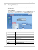
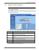

VAP Monitoring and Configuration
Dual-Band MobileAccessVE Instant Coverage Solution User Manual 50
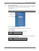
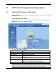
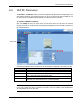
8.3 VAP RF Parameters
The Service 1 and Service 2 tabs provide the configurable RF parameters corresponding to the
VAP element selected in the network topology tree. Up to two service RF tabs are displayed, one
for each service. The displayed RF parameters are similar for both service tabs.
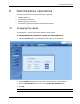
To view the VAP RF Parameters
Click the Config tab from the main menu bar and then select the VAP from the network
topology and click the
Service RF
tab. The parameters displayed in Service RF tabs correspond to
the selected element.
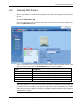
The following table provides a description of the RF parameters displayed in the Service RF tabs.
Parameter
Description
Type
Set according to unit type (e.g. EGSM /UMTS)
Service Control
Used to Disable (Off) or Enable (On) the service for the specific VAP
DL Pout Level
Normal – Pout from the VAP at normal level (according to the service)
Low – Pout from VAP is attenuated by 5 dB
DL Pout
Presents the measured output power
Antenna
Select External only if an external antenna is connected to this VAP.
Otherwise, the option should be set to Internal (default)
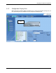
Note: VAP RF settings (Service Control, DL Pout Level, Antenna) are saved in the VCU associated
to the port to which the VAP is connected, such that in case you replace a VAP all parameters
are automatically set to the new VAP.
Selected VAP