
User's Manual
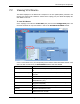
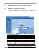
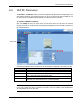

VCU Monitoring and Configuration
Dual-Band MobileAccessVE Instant Coverage Solution User Manual 47
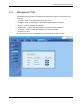
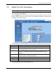
7.3 Master VCU RF Parameters
Note: The RF parameters are not displayed for control units functioning as Slave VCUs.
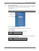
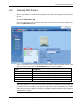
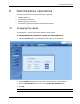
To access the Service RF tab
Click the Config tab from the main menu bar and then select the Master control unit from the
network topology and click the
Service RF
tab. The parameters displayed in Service RF tabs
correspond to the selected element.
The following table provides a description of the RF parameters displayed in the Service RF tabs.
Parameter
Description
Type
Set (read only) according to unit type (e.g. EGSM / UMTS)
DL CF*
DL Center frequency (from BTS). User defined, according to connected
service (EGSM / UMTS / CELL / PCS / DCS)
UL CF
UL center frequency (from BTS) – corresponding to defined DL Center
Frequency. Automatically assigned by the system according to the DL
frequency
Max Exp Pin*
Maximum expected input power from the BTS. Used for adjustment
procedure. Range: 0-33 dBm. User defined
Pin
Actual measured Pin (read only)
UL System Gain
Used for adjusting the UL system gain. Range: -15dB to +5dB
Service Control
Enables (On)/Disables (Off) the service
* Required parameters to be provisioned by the user.