
User's Manual

VCU Monitoring and Configuration
Dual-Band MobileAccessVE Instant Coverage Solution User Manual 46
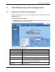
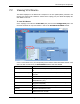
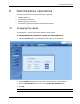
7.2 Viewing VCU Alarms
The alarms displayed in the Alarms tab correspond to the VCU (Master/Slave) selected in the
topology tree. When a VCU element is selected in the topology tree, the Alarm tab displays the
main alarms in the unit.
To view VCU Alarms
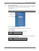
In the Topology Tree select the Control Unit (VCU) then click the Config(uration) tab in the
menu bar located at the top of the window. Refer to the VCU Alarms and Mask sub tab.
If one or more alarms occur, the corresponding Status indicator will be illuminated in RED. If the
VCU is OK and no fault occurs, the Overall Status indicator will show GREEN.
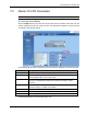
Alarm
Description
Service 1/2 DL RF Pwr Low
DL RF Power is lower by 15dBm (or more) from the Max Expected
Pin
Service 1/2 DL RF Pwr High
The input power exceeds the maximum expected Pin by more
than 3dB
Service 1/2 Service Off
User has disabled the service
Mismatch
Mismatch of services (e.g. CELL/PCS VAP connected to
EGSM/UMTS VCU, etc.)
Adjust
Cable (between VCU to VAP, or between Master to Slave),is too
long (over 100m/300ft)
Over Temperature
Temperature of unit exceeds normal range
CU Faulty
Hardware fault detected in VCU
Overall Status
Indicates Fault (RED) level if there are (unmasked) faults, or
GREEN if there are no faults