
User's Manual

Navigating the Web Access Application
Dual-Band MobileAccessVE Instant Coverage Solution User Manual 42
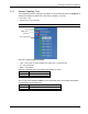
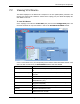
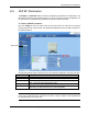
6.3.1 Network Topology Tree
The Configuration Network Topology Tree appears on the left hand side when the Config tab is
selected, and displays the Master VCU, Slave VCUs, and VAPs in two levels:
First Level – VCU
Second Level – Up to 12 VAPs
Note: The root is MobileAccess VE.
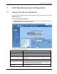
Each unit is assigned a Type Px-name:
Type – VCU-M, VCU or VAP (for Master VCU, Slave VCU or VE Access Pod)
Px - VCU port number
Name – user defined
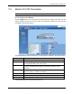
Each unit is displayed with a colored bullet that indicates its’ status:
Color
Indicates
Green
OK
Red
Alarm Condition
The root (the entire MobileAccessVE site) is also associated with a colored bullet that indicates
the overall status of the deployment:
Color
Indicates
Green
OK
Red
Alarm Condition in one or more VCUs or VAPs
Root
Master VCU –
first level
VAP – second level