
User's Manual


VCU Unit Installation and Provisioning
Dual-Band MobileAccessVE Instant Coverage Solution User Manual 31
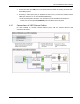
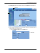
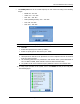
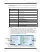
12. Verify that all the alarms are GREEN. Refer to the alarm descriptions in the table following
the figure below.
13. Mask irrelevant alarm conditions to avoid having them reflected to the overall status of the
unit.
Alarm
Description
Service 1 DL RF Pwr Low
RED - DL RF Power is lower by 15dBm (or more) from the
Max Expected Pin.
Service 1 DL RF Pwr High
RED - the input power exceeds the maximum expected Pin
by more than 3 dB.
Service 1 Service Off
User has disabled Service 1
Service 2 DL RF Pwr Low
RED - DL RF Power is lower by 15dB (or more) from the
Max Expected Pin.
Service 2 DL RF Pwr High
RED - the input power exceeds the maximum expected Pin
by more than 3 dB.
Service 2 Service Off
User has disabled Service 2
CU Faulty
RED - VCU fault. Remove and re-apply power to VCU. If
problem persists, replace VCU.
Over Temperature
Temperature of unit exceeds normal range.
Mismatch
Red – Mismatch of services (e.g. CELL/PCS VAP connected
to EGSM/UMTS VCU, VCU connected to slave VCU etc.)
Adjust
Cable (between VCU to VAP, or between Master to Slave),is
too long (over 100m/300ft)
Overall Status
Indicates Fault (RED) level or GREEN if there are no faults.
For Example
If the Dual-Band system is currently only being used to provide one service (while the
other service is disabled), the “Service Off” alarm can be masked (disabled).
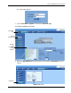
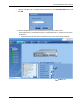
In the example below, the left dialog shows the alarm response if the Service 2 alarm is
NOT masked (enabled). In that case the Overall Status will be RED indicating a fault.
If the Service 2 alarm is MASKED (disabled), then the LED for the alarm will be RED; but,
the Overall Status will be GREEN – showing NO Fault.
Figure 4-3. Service2 Service Off Alarm – Not Masked Figure 4-4. . Service2 Service Off Alarm –Masked
Service2
Service
Off alarm
masked
(disabled)
Service2 Service
Off alarm
unmasked
(enabled)
Overall status RED
- accordingly