
User's Manual
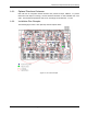

VCU Unit Installation and Provisioning
Dual-Band MobileAccessVE Instant Coverage Solution User Manual 19
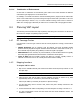
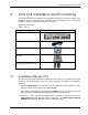
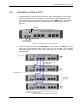
Note: The RF Source LED (see following figure) of the connected port on the Master VCU
should be lit GREEN, indicating that the Master VCU senses the RF signal from the source at
the expected level (according to Max Expected Pin). After connecting the capacity source, if
the LED remains RED verify that the Max Expected Pin is configured properly and service is
enabled.
4. Connect the Master VCU VAP ports to the Slave VCUs VCU/VCH ports via the patch-
panel that feeds the dedicated CAT-6/7 cabling system.
NOTE: After the Slave VCUs are connected (according to section
4 ), verify that that the Master
VCU VAP Status LEDs which correspond to the connected Slave VCUs complete initialization
(blinking light) and show a solid green light.
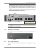
4.2 Auxiliary Connections
The auxiliary connections are performed through the Master VCU rear panel Alarms port. See
following figure.
4.2.1 Alarm Output Connections
The controller can provide Major and Minor Output Alarms. These alarms can be connected
directly to either the auxiliary input of the Base Station or to any additional dry-contact
application.
RF ports
Note: When functioning as a Master VCU,
the control units’ Ethernet Ports are
not relevant and should not be used.
VAP Ports 1-4; 5-8; 7-12
ACT LED
VAP Status
LEDs
Alarms port for auxiliary
connections