
User's Manual

VCU Unit Installation and Provisioning
Dual-Band MobileAccessVE Instant Coverage Solution User Manual 18
4 VCU Unit Installation and Provisioning
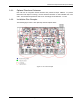
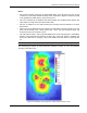
This section describes the installation and configuration procedures for VE Control Units (VCU)
located on each floor. These should be performed only after planning the floor coverage and
installation locations, as described in the previous sections.
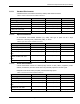
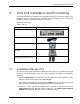
The VE VCU Kit includes:
Table 8: VCU Kit
Description
Unit
Dual-Band VE Control Unit (VCU) Kit
Power Cord
VE SW CD
Local Configuration Cable (crossed RJ-
45 cable)
Brackets for securing the VCU to a 19”
rack (shipped assembled to the VCU)
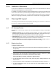
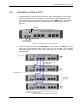
4.1 Installation of Master VCU
The VE Control Unit can be installed as a Master VCU and control up to (12) Slave VCUs and is
installed in the main IDF/telco closet. This section describes the Master VCU installation
procedures.
1. Install the Master VCU in the main Telco closet. The Master VCU can be installed in a rack,
placed on a shelf, or secured using the supplied bracket.
2. Apply power to the Master VCU and verify that the PWR LED is lit. Also verify that the unit
ACT LED completes initialization (blinking light) and shows a solid green light.
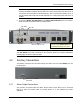
3. Connect (or request the service provider’s service personnel to connect) the provider’s
signal source (Macrocell, Microcell, Picocell, or BDA etc.) to the Master VCU front panel
RF ports (through passive interface). Power on the signal sources.