
User's Manual

Infrastructure Requirements and Layout Planning
Dual-Band MobileAccessVE Instant Coverage Solution User Manual 15
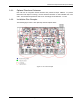
3.3.1.4 Combination of Environments
In areas with a combination of environments, place VAPs on the border between the different
environment types slightly closer to the denser area.
For example, in a cubical area with the outside wall having offices, simply locate the VAPs a little
closer
to the outside offices
to provide coverage through the office walls. (See VAPs 11 and 13 in
the floor plan map in section 3.4.3.). To ensure maximal coverage, VAPs can be re-located or
added. If a coverage gap is detected, the VAPs can be re-located until coverage gaps are filled.
3.4 Planning VAP Layout
The following section describes the steps of planning VAPs along the covered floor. At the end of
this section an example of a planning map is provided.
Note: It is highly recommended to use a floor plan when planning the VAPs locations.
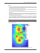
3.4.1 RF Coverage Factors
It is important to note the type of factors that can severely impact RF coverage, and should be
avoided:
Metallic Structures such as elevators, high file cabinets, and some moveable metallic
partitions severely degrade RF signals. All efforts should be made to locate VAPs in front of, or
above metallic objects (desks, filing cabinets) to allow the signal to propagate.
Wall Materials such as concrete, tile, and cinderblock, as well as bathroom fixtures typically
have fairly high signal attenuation and should be considered as dense spaces.
Types of Glass that have metallic coatings can affect RF coverage, typically exterior or
mirrored. However this issue is not normally encountered inside a building.
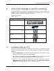
3.4.2 Mapping Locations
To map the VAP Locations
1. Map out the available Ethernet jack locations and mark all CAT-5e/6 drop locations on the
floor plan map.
TIP: The size and number of the ceiling tiles can be used to measure distances.
2. Using the floor plan and the VAPs coverage guidelines (as given in section 3.4.3), mark
approximately where you would like to place each VAP in the facility.
VAPs may be added (or removed) at anytime for optimal coverage.
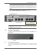
3. For each jack being used to connect a VAP, check if the jack is already connected to the
Ethernet switch. .
4. Connect the Ethernet cables corresponding to the selected jacks according to section 4.3.1.
5. It is also recommended to check the area where each VAP will be installed to ensure the
installation is feasible.