
User's Manual

Overview
Dual-Band MobileAccessVE Instant Coverage Solution User Manual 4
While operating as a Slave VCU:
Interfaces to Master VCU
Converges Wireless services, Ethernet and PoE and interfaces to VAPs
Management and control of connected VAPs
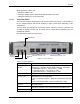
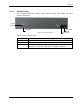
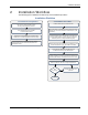
1.2.1.1 VCU Front Panel
The front panel supports the interfaces to the wireless services (two services – corresponding to
the two supported bands) and includes interfaces to VAPs or Slave VCUs (depending on the
configuration).
The front panel also interfaces to the Ethernet switch, includes a connector (VCU/VCH) for
receiving the wireless services from the Master VCU (in Master/Slave configuration) and the
management interface.
The following provides the front panel ports.
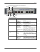
Figure 1-4. VCU Front Panel
Table 1: VCU Ports Description
Ports
Description
Service1
Service2
RF connections (two wireless services) to the service provider RF
equipment (e.g. picocells). N-Type female connectors. Coax cables.
EGSM-UMTS: Service 1 - UMTS, Service 2 - EGSM
CELL-PCS: Service 1 - PCS, Service 2 – CELL
DCS-UMTS: Service 1 – UMTS, Service 2 - DCS
Management
RJ45 WEB management connection.
VE Access Pod Ports
1-4; 5-8; 7-12
VAP/VCU port connections. RJ-45 connection to VAP/VCU through the
LAN infrastructure. CAT-5e/6 cables.
If VCU is connected as Master – these are connections to the Slave
VCUs.
If VCU is connected as Slave – these are connections to VAPs.
Ethernet Ports 1-4;
5-8; 7-12
Ethernet port connections to Ethernet Switch. Ethernet cables (used
only in Slave VCUs).
VCU/VCH
Used for connecting a Slave VCU to the Master VCU in a multi-tier
deployment (connects to one of the VAP ports of the Master VCU).
Reset
N/A in current version.
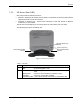
Ethernet Ports 1-4; 5-8; 7-12
VAP Ports 1-4; 5-8; 7-12
Management
Service 2
Service 1
VCU/VCH
Port