
User's Manual

Overview
Dual-Band MobileAccessVE Instant Coverage Solution User Manual 2
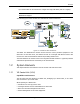
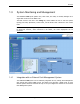
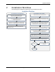
Multi-tier installation includes the Master VCU that supports up to 12 Slave VCUs. In this type of
installation the provider’s services are fed to the Master VCU through which the Slave VCUs are
controlled and managed.
Figure
1-2. Multi-Tier VE Installation
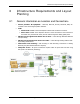
1.1 System Architecture
Main Elements - The MobileAccessVE solution is based on the following main elements:
VE Control Unit (VCU) – The control Unit can serve as either a Master or a Slave and
interfaces the other VCUs (in case of Master) or the VAPs (when serving as Slave). The Master
or Slave mode is automatically detected according to the VCU's physical connection. If a
connection to another VCU is detected, the VCU will automatically be identified as a Slave;
otherwise it will assume the role of a Master.
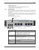
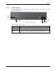
Master VE Control Unit (Master VCU) – installed in the main communication Telco
closet, interfaces to the service provider’s RF equipment, and provides secure, central
management to up to twelve VCUs, as well as all connected VAPs. In cases where no
Slave VCUs are required, VAPs can be connected directly to the Master VCU.
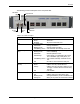
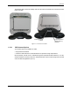
Slave VE Control Unit (Slave VCU) – installed in the telco/IDF closet and used to
expand coverage to additional floors. Each VCU interfaces the Master VCU and up to
twelve VAPs and twelve Ethernet connections.
The Slave VCUs distribute wireless service signals to each VAP along with PoE and (where
relevant) Ethernet signals from the Ethernet switch, throughout the existing CAT-5e
infrastructure.
The Slave VCUs are connected to the Master VCU using CAT-6 or 7 cables.
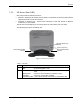
VE Access Pod (VAP)
– These are pluggable antennas distributed at strategic locations on
the floor to provide maximum coverage. VAPs provide RF coverage via integrated, internal
antennas. VAPs are also equipped with an interface for external antennas for special coverage
requirements. VAPs are remotely powered from the VCU using Power over Ethernet (PoE).
Local power is not required.