
User's Manual


Navigating the Management Application
Dual Band EnCOVER VE™ Instant Coverage Solution User Manual 43
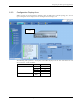
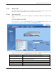
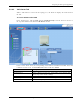
6.3.3 Configuration Display Area
When selecting an element (Master VCU/Slave VCU or VAP) in the network topology tree an icon
representing the unit is displayed in the Configuration tab display area
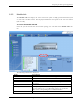
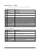
The following table provides a description of the LEDs displayed for the VCU and VAP icons and
that reflect the actual unit LEDs.
Unit LED No.
Master VCU/Slave VCU RF 2
IF 1
Port Pwr 12
Port Act 12
VAP Status
LEDs
2
Icon display
area