
User's Manual

VCU Unit Installation and Configuration
Dual Band EnCOVER VE™ Instant Coverage Solution User Manual 20
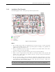
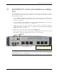
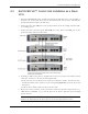
4.2 Auxiliary Connections
The auxiliary connections are performed through the Master VCU rear panel Alarms port. See
following figure.
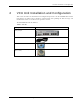
4.2.1 Auxiliary Input Connections
This Auxiliary connector can be used to monitor up to eight auxiliary connections such as fire-
alarm, air-conditioning alarm, open-door alarm, etc. The connections are normally open.
Connect the relevant alarms according to the connector pinout described in the following table.
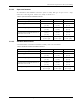
Table 8. Auxiliary Connector
Pin Number Auxiliary Alarm Pin Number Auxiliary Alarm
1, 26 8 8, 9 4
2, 3 7 10, 11 3
4, 5 6 12, 13 2
6, 7 5 14, 15 1
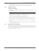
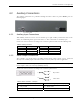
4.2.2 Alarm Output Connections
The controller can provide Major and Minor output alarms. These alarms can be connected
directly to the auxiliary input of the Base Station, or to any other dry-contact application.
Note: If only one alarm is required (Minor or Major) an external connection of a wire jumper
between pins 8 and 13 is necessary (normally closed)
Connect the relevant alarms according to the connector pinout below.
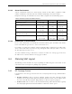
Table 9. Alarms Connector – used pins
8 – Major Error signal (normally closed) 7 – Minor Error signal (normally open)
11 – Major COM 12 – Minor COM
15 –Major Error signal (normally open) 13 – Minor Error signal (normally closed)
11
15
8
Major Alarm
12
7
13
Minor Alarm
A
larms port for auxiliary
connections