
User's Manual
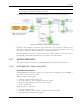

Infrastructure Requirements and Layout Planning
Dual Band EnCOVER VE™ Instant Coverage Solution User Manual 11
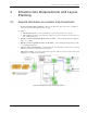
3.2 Infrastructure Requirements
1. IDF/Telco closet space for one or more VCUs depending on the number and locations of the
installed VCUs: (48.3 x 51.3 x 8.88 cm) per VCU.
Note: When planning the IDF/telco shaft, take the RF equipment (pico-cell/micro-cell or
BDA) and the VCU in to consideration.
2. 350 Watts of AC power to the VCU IDF/Telco closet.
3. Building infrastructure:
• Category 5e or CAT-6 cabling, Unshielded or Shielded Twisted Pair (UTP/STP)
• 24 AWG minimum diameter for CAT-5e cabling
• Dedicated CAT-6/7 STP cable from Master VCU to Slave VCUs with run lengths NOT
exceeding 100m (300ft).
• CAT-5e/6 UTP or STP cable from VCU to each VAP with run lengths NOT exceeding
100m (300ft). VAPs can be connected over existing CAT-5e/6 cabling infrastructure and
existing Ethernet jacks without affecting the LAN.
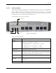
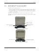
4. Master VCU Cable Connections:
• 2 x N-type female, 50 ohm interfaces to carrier equipment
• Up to 6 x RJ-45 interfaces to VCUs
• 1 x RJ-45 interface to Management
• 1 x D-Type 9 pins RS-232 interface for local craft
• 1 x D-Type 15 pins interface for External Alarms (dry contacts)
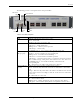
5. Slave VCU Cable Connections
• 1 x RJ-45 interface to Master VCU (not used in small single tier deployments)
• 12 x RJ-45 interfaces to VAPs
• 12 x RJ-45 interfaces to Ethernet Switch for LAN service “bridging”
• 1 x D-Type 9 pins RS-232 interface for local craft