
User's Manual

Infrastructure Requirements and Layout Planning
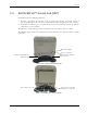
Dual Band EnCOVER VE™ Instant Coverage Solution User Manual 10
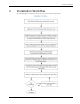
3 Infrastructure Requirements and Layout
Planning
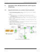
3.1 General information on Location and Connections
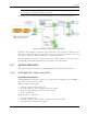
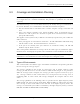
• Service provider’s RF equipment - Macro-cell, Micro-cell, Pico-cell, Femto-cell, BDA, etc.
connects to the VCU through a passive interface.
• VCUs:
• Master VCU installed at the main IDF/telco cabinet and connected to al VCUs.
• Slave VCUs installed at the IDF/telco cabinet of each covered floor and connected to
the cabling patch panel.
• Wireless service signal from Master VCU to VCUs – routed through dedicated Ethernet
CAT-6 or 7 cabling.
• Wireless service signal from VCUs to the VAPs – routed through existing Ethernet CAT-
5e/6 cabling infrastructure.
• VAP location and mounting - wall-mounting or desk-mounting. Connection to existing
Ethernet jack (and external antenna if required).
• VAP power source - No power connections required. VAPs are power fed from VCU using
PoE (Power over Ethernet) technology.
Figure 9. EnCOVER VE™ Multi-Tier Basic Architecture