
User's Manual

Overview
Dual Band EnCOVER VE™ Instant Coverage Solution User Manual 8
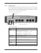
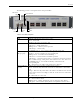
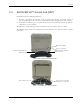
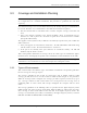
Figure 8: VAP LEDs
LED Description
Power Solid Green - Power supplied to VAP
Off - No power supplied to VAP
Activity Disabled - No power supplied to VAP or faulty VAP
Blinking Blue - Power on, VAP is initializing or in a fault condition
Solid Blue - Power on, RF signal received, unit operating
Fast Blinking Blue - User invoked “identify” command on corresponding VAP
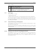
1.3.1 VAP Types
Two types of VAPs are available:
• VAP with internal antenna
• VAP with connector that interfaces to external antenna (for special coverage requirements)
The antenna type (internal or external) is automatically detected by the system so there is no
need for specific configuration. Each VAP can only transmit through the provided antenna option.
For example, if the VAP includes an external antenna connector the signal is only transmitted via
the external antenna connector.
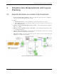
1.3.2 System Monitoring and Management
The EnCOVER VE™ system (Master VCU, Slave VCUs and VAPs) is centrally managed via a single
Web connection to the Master VCU.
The basic screen in the GUI is the monitor tab which enables the user to view the system
topology and setup parameters, the Control Units and all of the Access Pods that are connected
to the Control Units.
Note: When locally connecting to a specific VCU, only the VAPs connected to this VCU can be
monitored.
1.3.2.1 Integration with an External Fault Management System
The EnCOVER VE™ system can be seamlessly integrated into any existing Fault Management
(FM) system that supports SNMP events. The Master VCU generates SNMP event for each
relevant system alarm and forwards this trap to the pre-configured IP address of the external
Fault Management system.