
User's Manual


Connections I P/N 709C011101 I Page 26
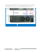
3.5.2 RF Connections
This section provides information describing the following connections:
• RF (SISO) and antenna monitoring connections between QX and SCU-F
• MIMO connections between QX and SCU-F
• SCU-F to broadband antenna infrastructure connections
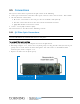
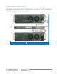
3.5.2.1 QX RF and Antenna Monitoring Connections
To connect the RF service and antenna connections (refer to Figure 3-20)
1. Connect the QMA to QMA RF jumper cables (provided with each ordered service module) to
the service specific QX RF QMA connector.
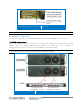
2. Route the cables through the assembled SCU-F Routing Bracket (see
3.4.1.4).
3. Connect the other side of the jumper cables to the relevant SCU-F low band (ports 1-4)
and/or high band (ports 5-8) QMA ports.
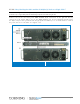
The connections shown in Figure
3-20 show an example of connections performed for the
CELL/PCS/700LTE/AWS services:
• QX High-frequency band mobile service to SCU-F High Ports (1 - 4) (e.g. AWS and PCS)
(shown in blue)
• QX Low-frequency band mobile service to SCU-F Low Ports (5 - 8) (e.g. CELL and
LTE700) (shown in red)
IMPORTANT! Terminate any unused ports.
NOTE: Refer to section
3.5.2.2for connections required for MIMO configurations.