
User's Manual


Connections I P/N 709C011101 I Page 24
3.5 Connections
The system connections required for the QX consist of the following:
• Fiber optic connections to the RF to fiber optic converter unit at the headend – BU or OCH
• RF and Antenna connections:
• RF service connections to the four port Service Combiner Unit (SCU-F)
• Antenna connections between the SCU and the broadband antennas
• (QX) AMU module connections to SCU
• Power – Local (AC) or Remote (DC)
The connections are described in the following sections.
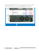
3.5.1 QX Fiber Optic Connections
Note: Keep in mind the rules for handling and connecting F/O cables. The F/O cables will be connected to the
associated BU/OCH in the communication room at a later phase.
To connect fiber optic cabling
1. (If not already installed) Install splice box near the QX chassis.
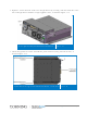
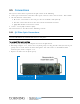
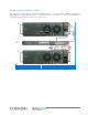
2. Referring to Figure
3-16, remove the tab (both parts) covering the fiber slot (located on port
panel) and set aside. Route the fiber through the slot and connect to the RHU SC/APC
To/From ports, Refer to Figure
3-18 .
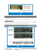
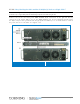
3. Replace the fiber slot tab (both parts).
Removing Fiber Slot Tab Figure 3-17