
User's Manual

QX Interfaces and Internal Modules I P/N 709C011101 I Page 4
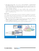
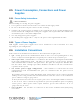
1.3 QX Interfaces and Internal Modules
1.3.1 QX Interfaces
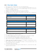
This section provides a full, detailed description of the QX unit and relevant interface
connections (Table
1-2) and LED indicators.
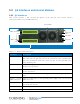
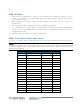
MobileAccessQX Front Panel Figure 1-4
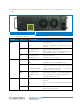
Table 1-1. QX Front Panel Interfaces
Interface Description
DB-15 AMU (Antenna Monitoring Unit) port. Connect to parallel port on SCU-F.
Note that only one QX unit port can be connected to the parallel SCU-F
port. For installations with more than one QX, cascade QX AMU ports
using IN/OUT ports.
IN/OUT AMU cascading ports. Use in case there are more than one QX units
connected to the SCU-F.
DB-9 RS232 serial connection (D-Type 9); Serves as AMU console port for
service personnel
Console Connect to network for AMU SW upgrade – for tech support personnel
only
Service specific
QMA connectors
Used for connecting to corresponding SCU-
F High band and Low Band
QMA connectors.
Optic Port Slot Slot used to guide the optic fiber to the RHU module fiber optic SC/APC
port inside the chassis.
AC In Local AC power connection: 100-240VAC (use either AC or DC)
DC In Remote DC power connection: 25 to 48VDC (use either AC or DC)
AMU connection
ports
AMU service
ports
Fan modules
AC power
DC power
Optic port
slot