
User's Manual

System Architecture I P/N 709C011101 I Page 2
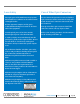
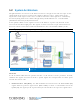
1.2 System Architecture
The QX and SCU-F are located at the floor level remote end. QX receives RF over optic service
signals from the head end, reconverts the signals to RF over copper, adjusts them to the
required level and outputs each service to dedicated interfaces. The signals are combined by
the SCU-F (along with services from other QX units) and distributed over a common DAS
(Distributed Antenna System) infrastructure.
In the uplink, cellular service signals received at the DAS are separated by the SCU-F and
routed to their dedicated QX ports. The signals are then converted to optic and forwarded to
the head-end for reconversion to RF and distribution to the relevant BTS or BDA systems.
Note: 3
rd
party equipment is sold separately (i.e. cabling, antennas).
QX Architecture Diagram Figure 1-2
Headend:
At the headend CMA elements provide interface to the wireless service provider’s network,
condition the signals and convert them to optical signals for transportation over fiber optics
towards the remote ends.
• Radio Interface Unit (RIU) - the RIU conditions and custom tunes the RF Downlink (DL)
signals from an operator’s signal source (BTS or BDA) to ensure a constant RF level. In the
Uplink (UL), the signal (at the required level) is routed back to the operator’s signal source.