Corning MobileAccess MobileAccessQX User Manual P/N: 709C0011101 REV: A00 Date: JANUARY2013
Preface Material RF Safety To comply with FCC RF exposure compliance requirement, adhere to the following warnings: Warning! Antennas used for this product must be fixed mounted on indoor permanent structures, providing a separation distance of at least 75 cm from all persons during normal operation.
Laser Safety Care of Fiber Optic Connectors Fiber optic ports of the MobileAccessQX system emit invisible laser radiation at the 1310/1550 nm wavelength window. Do not remove the protective covers on the fiber optic connectors until a connection is ready to be made. Do not leave connectors uncovered when not connected. The laser apertures /outputs are the green SC/APC Bulkhead adapters located on the front panel of the equipment.
Standards and Certification Corning MobileAccess products have met the approvals of the following certifying organizations: Company Certification ISO ISO 9001: 2000 and ISO 13485: 2003 Product Certifications US Radio Equipment and Systems: • FCC 47 CFR Part 22 – for CELL Frequency Band • FCC 47 CFR Part 24 – for PCS Frequency Band • FCC 47 CFR Part 27 – for 700 LTE and AWS Frequency Bands EMC • FCC 47 CFR Part 15 Subpart B Note: This equipment has been tested and found to comply with the limits for a C
EN 300 328 – for WLAN 802.11b/g 2.4GHz Frequency Band EN 301 893 – for WLAN 802.11a 5GHz Frequency Band EMC EN 301 489 Safety EN 60950UL 60950 CAN/CSA-C22.2 No.60950 UL 2043 Laser Safety CDRH 21 CFR 1040.10, 1040.11 (Except for deviations per notice No.50, July 26, 2001) IEC 60825-1, Amendment 2 (January 2001) EN 60825-1 About this Guide and Other Relevant Documentation This user guide describes how to perform the physical installation of the MA2000 systems.
List of Acronyms BDA Bi-Directional Amplifier BTS Base Transceiver Station BTSC Base Transceiver Station Conditioner BU Base Unit DL Downlink RU Remote (Hub )Unit RIU Radio Interface Unit RBS Radio Base Station UL Uplink List of Acronyms P/N: 709C0011101 Page VI
Table of Contents Preface Material ........................................................................................................................II RF Safety .......................................................................................................................................... II Laser Safety ..................................................................................................................................... III Care of Fiber Optic Connectors ....................
3.3 Inserting an RHU/AO Module in to QX Chassis ............................................................................. 14 3.4 Mounting ................................................................................................................................... 16 3.4.1 Rack Mount Installations ................................................................................................... 16 3.4.1.1 Plan the rack installation ..................................................................
1 Introduction MobileAccess2000 QX (QX) is a member of the MobileAccess2000 family. It is a compact, modular, cellular indoor coverage remote unit supporting up to four services (currently, CELL/PCS, LTE and AWS). 1.1 Key Features and Capabilities All services are received from the head-end, over a single optic fiber and reconverted to RF for convergence and distribution over a common DAS antenna infrastructure. • Multi-Service Platform - Supports up to four services.
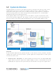
1.2 System Architecture The QX and SCU-F are located at the floor level remote end. QX receives RF over optic service signals from the head end, reconverts the signals to RF over copper, adjusts them to the required level and outputs each service to dedicated interfaces. The signals are combined by the SCU-F (along with services from other QX units) and distributed over a common DAS (Distributed Antenna System) infrastructure.
• RF to Optic converter unit – this can either be a Base Unit (BU) or an Optical Control Head End Unit (OCH), where the OCH is QX model specific. These are wideband units that convert the RF Downlink (DL) signals from the RIU into optical signals for routing over single or multi-mode fiber optic cabling (SMF/MMF) to/from the QX units located at the remote locations up to 2Km away.
1.3 QX Interfaces and Internal Modules 1.3.1 QX Interfaces This section provides a full, detailed description of the QX unit and relevant interface connections (Table 1-2) and LED indicators. Fan modules AMU connection ports Optic port slot DC power AC power AMU service ports MobileAccessQX Front Panel Figure 1-4 Table 1-1. QX Front Panel Interfaces Interface Description DB-15 AMU (Antenna Monitoring Unit) port. Connect to parallel port on SCU-F.
The QX front panel supports three groups of LEDs: system level, for the RHU and for each Addon unit. MobileAccessQX Front Panel Figure 1-5 Table 1-2: LEDs Descriptions: Module LED Description QX (system level) Power Steady Green: Required power is supplied to AMU module of QX chassis Off: No power supplied to AMU module of QX chassis Steady Green: AMU module SW initialized Blinking Green: AMU module SW is initializing (blinks for the duration of approx.
1.3.2 QX Main Internal Modules The QX main components consist of the following internal modules: • Remote Hub Unit (RHU) – service specific unit, supports two voice services, converts the optical signals received from the BU/OCH to RF signals (and vice versa) and routes them to the coax antenna infrastructure (via the Four Port Service Combiner Unit – SCU-F).
1.4 SCU-F Interfaces The SCU-F is a passive unit which interfaces to the QX RF service ports and internal AMU module and to the DAS infrastructure. All of the interfaces are located on the front panel (shown in Figure 1-6). DB-15 port to QX DB-15 port Antenna Ports 1-4 SCU-F Front Panel Low Band (1-4) ports; High Band (5-8) ports Figure 1-6 Table 1-4.
2 Installation Guidelines 2.1 Infrastructure Preparation This following installation rules are based on the assumption that site survey and installation planning (including power requirements) have been completed. 2.2 Installation Requirements The infrastructure preparation consists of two main phases: Floor Planning: Planning the distribution of the antennas on each floor to provide the required coverage.
x 2.3.2 RF Rules • When using the MobileAccess system in an environment in which other indoor coverage systems are installed, it is recommended (where possible) that the antennas are placed at least two meters apart • When bending coax cables, verify that the bending radius does not exceed the coax specifications. • Use wideband antennas supporting a range of 800Mhz to 2500Mhz • Use a VSWR meter (i.e. Site Master or equivalent) for checking coax cables, including the antennas. (<2).
2.4 Fiber Optic Rules • Either single mode or multimode fiber can be used with QX products. • Only Multimode fiber, 50/125 or 62.5/125um complying with ANSI/TIA/EIA-568-B series, EN50173-1 or ISO/IEC 11801 can be used. The fiber length can be up to 300 meters assuming the following qualifications: • All fiber in a given length of fiber must be of the same core diameter. • All Bulkhead adapters must be Single mode SC/APC (Green) adapters.
2.5 Power Consumption, Connections and Power Supplies 2.5.1 Power Safety Instructions SAFETY WARNINGS When installing or selecting the power supplies: • It is required to install a circuit breaker of 7.5A for the DC supply circuit. • Be sure to disconnect all power sources before servicing. • Calculate the required power according to the requirements of the specific installation and then determine the configuration of the power supplies.
3 System Installation The following sections provide an overview of the installation procedure for the QX and an SCU-F unit. Note: The QX must be installed with the SCU (in rack installations - preferably below the SCU).
3. Verify that all supplied items have been received for the QX (see Table 3-1) and Table 3-2). Table 3-1: Package Contents Kit Item P/N Description QTY. QX QX chassis - Empty chassis 1 AC Power Cable 705900007 Black, Straight, USA Length=1.8-2.5m , 110V DC Power Cable 705A030821 DC, Power Cable Edges. Length=5m Flat Cable 705900003 QMA Cable ,UL, 1 Open 1 RJ45 to RJ45 communication cable. Length 2m-2.15m 1 705A042101 QMA to QMA straight cable, R/A,0.
3.3 Inserting an RHU/AO Module in to QX Chassis The QX chassis and Remote Hub Unit (RHU) and Add-On (AO) modules are provided separately, whereas the modules must be inserted in to the chassis. This requires opening the QX chassis front panel door and inserting the modules into their respective slots. The RHU/AO modules are hot swappable and can be inserted either before or after the system installation. To insert an RHU/AO Module 1. Open the QX door, by unscrewing the two captive screws.
Positioning New Module in Designated Slot Figure 3-3 4. Push the module all the way back until it “clicks” in to the chassis backplane. 5. Close ejectors and close both captive screws to secure the module in place. Refer to Figure 3-4. 6. For each Add-On module, connect the internal DC power feed to the module DC power connector. Refer to Figure 3-4. Securing Module in Slot and DC Connections Figure 3-4 NOTE: The RHU service module does not have an internal power feed connection.
3.4 Mounting 3.4.1 Rack Mount Installations 3.4.1.1 Plan the rack installation NOTE: The unit can also be wall mounted using dedicated brackets (ordered separately). For wall mounted units – it is recommended to install the service modules first. 1. Verify that the height of the rack can support QX unit being installed, as well as additional equipment, SCU-F, AC or DC power, and space for the broadband coax connection. Also consider room for future expansions. 2.
3.4.1.2 Rack Installation Safety Instructions Review the following guidelines to help ensure your safety and protect the equipment from damage during the installation. • Only trained and qualified personnel should be allowed to install or replace this equipment. • Verify that ambient temperature of the environment does not exceed 50°C (122°F) • To maintain a low center of gravity, ensure that heavier equipment is installed near the bottom of the rack and load the rack from the bottom to the top.
SCU-F Pre-assembled Rack Ears Figure 3-7 3.4.2 Wall Mount Installation There are two wall mount installation options for the QX unit, whereas the SCU-F can also be mounted on top of the QX chassis so as to accommodate connections between the units: a. Horizontal Wall Mount (provided with QX) - QX unit is mounted in a horizontal alignment so that the front panel interfaces face towards the front (as in rack installations). See 0. b.
3.4.2.1 QX Horizontal Wall Mount Installation To mount the QX horizontally on the wall 1. Mark and drill the installation holes in the wall, using the bracket as a guide. There are two options, as shown in Figure 3-9: • Holes A1 and A2 are used for securing the brackets to the wall in a fixed position • Holes B2, B2 and B3 are used for hanging the assembly on anchors QX Horizontal Wall Mount Bracket Holes Figure 3-9 2.
3. Optional – mount the SCU-F unit on to the QX chassis: • Remove the QX side rack ears (pre-assembled) to access the holes required for assembling SCU-F • Secure each SCU-F bracket to the side of the QX chassis using the six (6) supplied screws, as shown in Figure 3-11. SCU-F to QX Assembly for Wall mount Figure 3-11 Installation 4.
3.4.2.2 QX Vertical Wall Mount Installation Note: Vertical Wall Mount brackets are ordered separately (P/N AK-QX-ENC-WMT-V). To mount the QX vertically on the wall 1. Verify that the following items are included in the accessory kit: Item QTY. Vertical Wall Mount Bracket for QX chassis Screw,4-40X5/16',Flat-HD, 100', Philips, Nerosta Image 2 16 2.
3. Assemble the vertical wall mount brackets on to the sides of the QX chassis using the eight (8) provided screws, as shown in Figure 3-14 Vertical Wall Mount Bracket Assembly Figure 3-14 Note: You may want to mark the mounting holes on the wall (according to brackets) prior to mounting. 4. Select the appropriate location on wall for the QX unit. Verify that: • There is enough free space around the unit for ventilation • Location enables opening the enclosure door to the side 5.
6. Optional – mount the SCU-F unit on to the QX chassis by securing each SCU-F bracket to the side of the QX chassis with the six (6) supplied screws, as shown in Figure 3-15. SCU-F to QX Assembly for Wall mount Installation Figure 3-15 7. Mount the QX chassis on the wall with the panel interfaces facing towards the side, as shown in Figure 3-16.
3.5 Connections The system connections required for the QX consist of the following: • Fiber optic connections to the RF to fiber optic converter unit at the headend – BU or OCH • RF and Antenna connections: • RF service connections to the four port Service Combiner Unit (SCU-F) • Antenna connections between the SCU and the broadband antennas • (QX) AMU module connections to SCU • Power – Local (AC) or Remote (DC) The connections are described in the following sections. 3.5.
Routing Fiber to Connection Port Figure 3-18 Note: See section 3.5.1.1 for MIMO connections to RF to Fiber optic converter unit (BU/OCH). 3.5.1.1 MIMO Configurations Two QX units supporting the LTE700 and AWS bands can provide MIMO service coverage. For MIMO configurations Connect the fiber optic port of each of the two QX units’ supporting the LTE 700 and AWS (SISO) bands to a different BU/OCH optic module (see section 3.5.1 for description of connections).
3.5.2 RF Connections This section provides information describing the following connections: • RF (SISO) and antenna monitoring connections between QX and SCU-F • MIMO connections between QX and SCU-F • SCU-F to broadband antenna infrastructure connections 3.5.2.1 QX RF and Antenna Monitoring Connections To connect the RF service and antenna connections (refer to Figure 3-20) 1.
04. Connect the QX internal AMU module (for antenna sensing) to the SCU by connecting the DB15 female connector to the corresponding SCU DB15 female connector, using corresponding cable provided with the SCU-F (P/N 705A042301). See Figure 3-20.
3.5.2.2 RF MIMO Connections to SCU-F Two QX units supporting the LTE700 and AWS bands can be deployed in a MIMO configuration. The LTE700 and AWS RF service ports of both QX units are connected to the corresponding low band and high band SCU-F ports. See Figure 3-21.
3.5.2.3 Daisy Chaining the AMU modules of Multiple QX Units to a Single SCU-F NOTE: If installing more than one QX unit, they can be interconnected so that the antenna sense function is performed by a single AMU (Antenna Monitoring Unit) located inside the QX unit. Connect one of the two front panel ANT. Sense1 RJ45 connectors of the QX unit directly connected to the SCU-F DB-15 port to the ANT. Sense1 port of the additional QX unit using the RJ45 to RJ45 cable provided with the QX (P/N 705900003).
3.5.2.4 SCU-F to Broadband Antenna Connections To connect the broadband antennas The QX is connected to the antenna infrastructure via the Service Combiner Unit (SCU-F). Connect the SCU-F front panel N-Type RF Antenna Ports to the broadband antennas. See Figure 3-23. Note: Terminate any unused antenna ports with 50 ohm terminators. SCU-F to Antennas Connections Figure 3-23 3.5.3 Grounding the QX Unit Ground the QX cabinet via the grounding lug located on the rear.
3.5.4 Power Connections The QX supports both local powering (100-240VAC) and remote powering (25 to 48VDC) options. Both types of power cables are provided with the unit (see section 3.2). Connect the power source to the QX using either Local or Remote power (both are supported): AC In - Local Power: 100-240VAC (Integrated AC/DC converter) DC In - Remote Power: 25 to 48VDC Refer to for Figure 3-25 location of power connectors.
3.6 Verifying Normal Operation Upon powering up the QX remote unit: • Confirm the fans are working after powering • Verify normal operation: Module LED Description QX Power Steady Green: Required power is supplied to AMU module of QX chassis Off: No power supplied to AMU module of QX chassis Steady Green: AMU module SW initialized Blinking Green: AMU module SW is initializing (blinks for the duration of approx.
LED Indication of Normal Operation Figure 3-26 Verifying Normal Operation I P/N 709C011101 I Page 33
4 Maintenance This section provides maintenance information on the following: • Replacing existing RHU/AO modules currently in QX chassis • Replacing the QX chassis fan modules (in case of faulty fans) 4.1 Replacing an RHU/AO Module This section describes how to replace an existing RHU and/or RHU/AO module. The RHU and AO modules are easily removed from/added to the QX chassis, while the procedure does not require powering off the unit (hot-swap). To Replace an RHU/AO Module 1.
2. To remove a module: NOTE: For partial configurations, a “dummy” module is inserted in the unused service module slot. Does not include connections. • Disconnect F/O (RHU) or DC power connection (Add-On) – where relevant • Open the captive screws securing the module in place • Open the ejectors and Pull the module out (using the handle) Removing Service Module Figure 4-2 3. To insert a module – refer to section 0 4.
4.2 Replacing Fan Module In case of faulty fans, they are easily replaced while the procedure does not require powering off the unit (hot-swap). To replace faulty fan(s) 1. Unscrew the four screws securing the fan to the chassis door. See Figure 4-3. Unscrewing Fan Module Screws Figure 4-3 2. Pull out the fan module and disconnect the cable. See Figure 4-4. Disconnect cable Removing Existing Fan Module Figure 4-4 3. Connect new fan module. 4.
Insert fan module so that the metal plates are on each side Inserting New Fan Module Figure 4-5 5. Tighten the four fan module screws so it is secured to the QX front door panel.
5 Appendix A: System Specifications RF Parameters Supported Services Technologies Band Frequency Range Uplink (UL) Downlink (DL) CDMA/WCDMA**/TDMA/GSM/LTE* CELL800 824-849 869-894 CDMA/WCDMA**/TDMA/GSM/LTE* PCS1900 1850-1915 1930-1995 WCDMA**/LTE* AWS1200 1710-1755 2110-2155 700 MHz 698-716 728-746 776-787 746-757 LTE (*)WCDMA service is based on 3GPP standards, LTE service may deployed in the future due to Frequencies re-farming planned by the Carriers as well (**)WCDMA service is b
RF Parameters per Service at Antenna Port of Four Port Service Combiner Unit (SCUF) The RF Parameters listed in the tables in this section reflect the specifications at each of the four antenna ports of the SCU-F when combined with the QX.
Absolute Maximum Rating Total RF Input Power to BU/OCH 10 dBm Total RF Input Power to QX RHU Module 20 dBm out-of-band; -10 dBm in-band Optical Specifications Optical Output Power < 3.0 mW Max. Optical Budget 2 dB for fiber + 1 dB for connectors (assumed) = 3 dB total. 300 m Multi-mode Optical Loss per Mated-pair Connectors 0.5 dB (max) Optical Connectors SC/APAC Fiber Type Single Mode Fiber (SMF): 9/125 µm Multi Mode Fiber (MMF): 50/125 µm or 62.
Standards and Approvals Laser Safety CDRH 21 CFR 1040.10, 1040.11 (Except for deviations per notice No.50, July 26, 2001) IEC 60825-1, Amendment 2 (January 2001) EN 60825-1 CE Radio Equipment and Systems EN 301 502 – for GSM / EGSM Frequency Bands EN 300 328 – for WLAN 802.11b/g 2.4GHz Frequency Band EN 301 893 – for WLAN 802.11a 5GHz Frequency Band EMC EN 301 489 FCC Radio Equipment and Systems: FCC 47 CFR Part 22, 24, 27, 90 EMC: FCC 47 CFR Part 15 Subpart B Safety EN 60950UL 60950 CAN/CSA-C22.
System Component Specifications Quad-Service Package (QX) Supported Services CELL850; PCS1900; LTE700; AWS2100 Ports To Service Combiner Unit (SCU): (4) 50Ω QMA ports To Base Unit/Optical Control Hub (OCH-QX): AMU Master-Slave connections (2) SC/APC ports Local connection to AMU module for SW DL (for service personnel): To SCU-4: (1) RJ45 port RS232 local connection to AMU module (for service personnel): (1) DB9 connector Power (2) RJ45 ports (1) DB15 connector Local Power: 100-240VAC (Integra
6 Appendix B: Ordering Information NOTE: The information listed below is updated up to the document publishing date. Refer to the QX datasheet for the most updated ordering information.