User Manual MobileAccessVE LTE 700 MHz MIMO Instant Coverage Solution User Manual P/N: 709C006202 REV: A00 Date: OCT 2010 UM_VE LTE 700 MHz MIMO_709C006202_Rev A00_08OCT10.
Preface Material MobileAccess 8391 Old Courthouse Road, Suite 300, Vienna, VA 22182 Tel: +1(866)436-9266, +1(703)848-0200 TAC: +1(800)787-1266, Fax: +1(703)848-0280 http://www.MobileAccess.
Preface Material Preface Material © Copyright 2010, MobileAccess Networks Inc. All Rights Reserved. This document contains confidential and proprietary information of MobileAccess and may not be copied, transmitted, stored in a retrieval system or reproduced in any format or media, in whole or in part, without the prior written consent of MobileAccess.
Preface Material Returns In the event that it is necessary to return any product against above warranty, the following procedure shall be followed: 1. Return authorization is to be received from MobileAccess prior to returning any unit. Advise MobileAccess of the model, serial number, and discrepancy. The unit may then be forwarded to MobileAccess, transportation prepaid. Devices returned collect or without authorization may not be accepted. 2.
Preface Material Certification and Compliance to Standards Category Standards Safety: IEC 60950-1: 2003; UL-60950-1:2003; CAN/CSA – C22.2 No 60950-1-03 EMC: 47CFR 15.
Preface Material About This Guide This guide provides essential product functionality with all the information necessary for proper installation and configuration of the MobileAccessVE system.
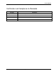
Table of Contents 1 Overview .............................................................................................................................1 1.1 Key Features and Capabilities ....................................................................................................... 2 1.2 System Architecture ..................................................................................................................... 3 1.3 System Elements ..................................................
Table of Contents 4.3.1 Shifting Relevant Ethernet LAN Connections ....................................................................... 21 4.3.2 Operation with LAN utilizing Power over Ethernet (PoE) ...................................................... 23 4.4 Provisioning the VE Control Unit.................................................................................................. 23 4.4.1 Configure the Computer IP Parameters .....................................................................
Table of Contents 6.4 Management Tab ....................................................................................................................... 58 7 VCU Monitoring and Configuration.................................................................................59 7.1 Viewing VCU General Information ............................................................................................... 59 7.2 Viewing VCU Alarms ........................................................................
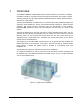
1 Overview The MobileAccessVE LTE 700 MHz MIMO solution provides enhanced, cost effective, in-building LTE MIMO coverage for any small-to-large sized enterprise environment. This solution is quickly and easily deployed using the existing Ethernet cabling infrastructure without affecting existing LAN services or performance.
Overview Multi-tier installation includes the Master VCU that supports up to 12 Slave VCUs. In this type of installation the provider’s services are fed to the Master VCU through which the Slave VCUs are controlled and managed. Figure 1-2. Multi-Tier VE Installation 1.1 Key Features and Capabilities Simple Installation - Deployed in only a few hours, with minimum disturbance to the enterprise. VAPs connect over existing CAT-5e/6 cabling infrastructure and existing Ethernet jacks.
Overview 1.2 System Architecture Main Elements - The MobileAccessVE solution is based on the following main elements: VE Control Unit (VCU) – Provides interface to up to 12 VAPs, and the central interface for managing the VE deployment. In Master/Slave mode, it can serve to expand the network coverage with additional VCUs serving as Slaves and a single control point at the Master. Slave mode is automatically detected when a Slave VCU detects that it is connected to the Master VCU.
Overview The Master VCU distributes the wireless MIMO services from the service provider’s equipment to the Slave VCUs. At the Slave VCUs, the wireless MIMO services are converged with Ethernet service and routed to the VAPs via the Ethernet LAN CAT-5e/6 cabling infrastructure.
Overview Table 1: VCU Ports Description Ports Description RF connections (two TDD MIMO channels) to the service provider LTE Signal Source equipment. N-Type female connectors. Coax cables. MIMO1 MIMO2 Note: When supporting SISO service – only MIMO 1 connector is relevant. Management RJ45 web management connection. VAP/VCU port connections. For Master VCU – Connections to Slave VCUs or VAPs. For Slave VCU – Connections to VAPs.
Overview 1.3.1.2 VCU Rear Panel The rear panel includes the following: power switch, AC input, AUX alarms, and service personnel connections. Console Connector AUX Alarms Figure 1-5. VCU Rear Panel PWR On/Off Switch AC Connector Table 3: VCU Rear Panel Description Connector Description Console RS232 local connection for service personnel (D-Type 9) Alarms Power Input 1.3.2 AUX alarms connections(See section 4.2.1.1). In Master/Slave configuration - relevant only for Master VCU.
Overview The following figure shows the desktop VAP. Front View Blue LED (Activity and Identify) Green Led (Power) External Antenna SMA Connector External Antenna SMA Connector Figure 1-6.
Overview 1.4 System Monitoring and Management The MobileAccessVE system (Master VCU, Slave VCUs, and VAPs) is centrally managed via a single Web connection to the Master VCU. The basic screen in the GUI is the Config tab, which enables the user to view the system topology and setup parameters, Control Units, and all Access Pods connected to the Control Units. Note: When locally connecting to a specific Slave VCU, only the VAPs connected to this VCU can be monitored.
Installation Workflow 2 Installation Workflow The following figure summarizes the main steps of the installation procedure: Installation Workflow 1. Infrastructure Preparation 2. Installation Procedure Plan the floor coverage and VAP locations according to the type/density of the site. Install the Master VCU in the IDF/telco shaft. Check that Ethernet jacks are available in all planned VAP locations.
Infrastructure Requirements and Layout Planning 3 Infrastructure Requirements and Layout Planning 3.1 General Information on Location and Connections Service provider’s RF equipment - macrocell, microcell, picocell, femtocell, BDA, etc. connects to the VCU through a passive interface. VCUs: Master VCU installed at the main IDF/Telco cabinet and connected to all VCUs.
Infrastructure Requirements and Layout Planning 3.2 Infrastructure Requirements Ethernet standards specify that the maximum distance between an Ethernet switch and an appliance (computer, WLAN AP, etc) should not exceed 100m (300ft).
Infrastructure Requirements and Layout Planning 3.3 Coverage and Installation Planning Note: The following section provides information required for planning the VAP installation on a single floor. In a multi-tier installation, this procedure is performed for each individual floor. The maximal coverage area of each VAP is affected by the density and type of environment being covered.
Infrastructure Requirements and Layout Planning 3.3.1.1 Standard Environment A traditional office environment with offices, hallways, and scattered cubicles. Table 5: Standard Environment Installation Distances 3.3.1.2 Signal Propagation from VAP 56 feet (19 m) Recommended Spacing between VAPs 112 feet (38 m) Recommended Maximum distance of VAPs from outer walls 56 feet (19 m) Coverage area per VAP 9,900 sqft (920 sqm) Open Environment An environment with minimal obstacles (e.g. walls).
Infrastructure Requirements and Layout Planning 3.4 Planning VAP Layout The following section describes the steps of planning VAPs along the covered floor. At the end of this section an example of a planning map is provided. Note: It is highly recommended to use a floor plan when planning the VAPs locations. 3.4.
Infrastructure Requirements and Layout Planning 3.4.4 Installation Plan Example The following figure shows a floor plan map with all required marks: Figure 3-2. Floor Plan Example Notes: The red VAP coverage circles have an approximate radius of 41, 56, and 64 foot (13.5, 19, and 21 meters) for the small, medium, and large circles respectively, which are drawn according to the guidelines given in section 3.3.1.
Infrastructure Requirements and Layout Planning The following figure depicts an actual measured quantified coverage of a floor area planned according to the above rules. Figure 3-3. Distributed VAPs propagation, 12dBm output power @ 1.
VCU Unit Installation and Provisioning 4 VCU Unit Installation and Provisioning This chapter describes the installation and basic configuration procedures for VE Control Units (VCU) located on each floor. In addition, this chapter describes the how to shift the relevant Ethernet connections required for the VAPs. These steps should only be performed after planning the floor coverage and installation locations, as described in the previous sections. 4.
VCU Unit Installation and Provisioning 4.2 VCU Physical Installation This section describes the physical installation and connections of the Master VCU, Slave VCUs and the VAP Ethernet connections to the relevant VCUs. 4.2.1 Master VCU Installation The VE Control Unit can be installed as a Master VCU and control up to (12) Slave VCUs and VAPs and is installed in the main IDF/Telco closet. This section describes the Master VCU installation procedures.
VCU Unit Installation and Provisioning VAP Status LEDs RF Ports ACT LED VAP Ports 1-4; 5-8; 7-12 Note: When functioning as a Master VCU and supporting only Slaves (no VAPs), the control units’ Ethernet Ports are not relevant. The Ethernet ports are only relevant when supporting mixed mode – Slave VCUs and VAPs. Note: After the Slave VCUs are connected (according to section 4.2.
VCU Unit Installation and Provisioning Connect the relevant alarms according to the connector pinout below. 11 15 Major Alarm 8 12 7 Minor Alarm 13 Table 9. Alarms Connector – used pins 8 – Major Error Signal (Normally closed) 4.2.2 7 – Minor Error Signal (Normally open) 11 – Major COM 12 – Minor COM 15 –Major Error Signal (Normally open) 13 – Minor Error Signal (Normally closed) Slave VCU Installation 1.
VCU Unit Installation and Provisioning Figure 4-2. Master and Slave VCU Connections 3. Connect the Slave VCU VAP ports to the patch-panel that feeds the existing structured CAT5e/6 cabling system. 4. According to VAPs layout plan, as explained in section 3.4.2, connect the Ethernet switch cables. (See section 4.3 for more detailed explanation). If the requested jack is already in use, disconnect it from the Ethernet switch and reconnect it to the corresponding Ethernet port in the Slave VCU front panel.
VCU Unit Installation and Provisioning For VAPs installed on currently INACTIVE Ethernet ports, connect as follows. Note: After the Slave VCUs are installed and connected to the correct ports in the patch panels, please proceed with the VAP installation as described in chapter 5 . However, it is recommended to complete the VCU provisioning first (See section 4.4) because when installing the VAPs they will instantly provide the wireless service and the installer will be able to check the coverage.
VCU Unit Installation and Provisioning 4.3.2 Operation with LAN utilizing Power over Ethernet (PoE) Power over Ethernet (PoE) is a technology that enables passing electrical power over the Ethernet cabling. Power can either come from a PoE-enabled Ethernet device (e.g. switch) or from a “mid-span” device built specifically for "injecting" power into the Ethernet cabling. PoE can operate over two different pairs in a CAT-5e/6 cable. These two methods are referred to as “alternative a” and ”alternative b”.
VCU Unit Installation and Provisioning The Local Area Connections Properties dialog box appears with the General tab displayed by default. 4. In the Items list, select “Internet Protocol (TCP*IP)” and click the Properties button. 5. The “Internet Protocol (TCP/IP) Properties” dialog appears. Note: The Master VCU is supplied with the default IP address 192.168.1.1. In order to communicate with the unit, it is necessary to assign your computer a Static IP address in the same subnet: 192.168.1.2 to 192.
VCU Unit Installation and Provisioning 2. Open a web browser and type the Master VCU IP address in the address bar (Default: 192.168.1.1). Note: If you have forgotten the VCU IP address and/or want to change it, it can be retrieved via the IP Recovery Tool application provided on the Setup CD. See 9.2. The Login window appears. 3. Type the User Name “engineer” and enter the Password “eng”. The MobileAccessVE Web GUI appears.
VCU Unit Installation and Provisioning Main Menu Bar Network Topology Tree Sub-tabs that correspond to each main tab 4. Choose the Management tab in the main menu bar and click the IP Settings tab on the side bar. IP Settings Modify Button Note: See section 6.4 for a description of the Management tab. 5. Click the Modify button to define the STATIC IP Address according to existing LAN. Note: After the initial IP configuration, the Master VCU can be accessed remotely via Ethernet.
VCU Unit Installation and Provisioning Set the Static IP address parameter (DHCP is not currently available) Default definitions: • • • The Default IP Address: 192.168.1.1 The Default Subnet Mask: 255.255.255.0 The Default Gateway: 192.168.1.254 Click OK. 6. Log out and then log in again with the new IP settings. 7. Select the Config tab in the main menu bar. Note: See section 6.3 for a complete description of the Config tab.
VCU Unit Installation and Provisioning 8. The Master VCU appears in the Network Topology Tree as VCU-M. Select the Master VCU by clicking on it. Config Tab Master VCU 9. Before configuring the Master VCU it is recommended to give the unit an identifiable name. To assign the Master VCU an identifiable name: Select the Module Info Tab and click the Modify button. Click Modify button.
VCU Unit Installation and Provisioning Type the unit name in the Controller Name dialog and click OK. Note: Up to 17 alpha- numeric characters are allowed. 4.4.3 Setting RF Parameters In a Master-Slave mode (multi-tier architecture) the RF parameters are only configured for the Master VCU unit. Set the RF parameters according to the LTE Signal Source transmission configuration (MIMO or SISO). Each type of configuration is defined through a dedicated tab.
VCU Unit Installation and Provisioning Note: The MIMO DL CF parameter is Read Only and pre-defined for the supported 10 MHz block. The MIMO DL CF parameter defines the same DL central frequency from the Base Station for Channel 1 and Channel 2. 2. Define Max expected power of BTS (0-33dBm). 3. Define UL System Gain (-15 to 5dB) Notes: 1. Max expected Pin parameter can be obtained from your service provider. 2. The remaining parameters are predefined to their default values.
VCU Unit Installation and Provisioning Notes: 1. Max expected Pin and SISO DL CF parameters can be obtained from your service provider. 2. The remaining parameters are predefined to their default values. (Service Bandwidth is set to 10 MHz). 3. Any updates of the service definition (DL CF or Service Mode) are sent to all connected VAPs. 4.4.4 Verifying System Operation To verify proper operation of the system, refer to the VCU Alarms and Mask sub-tab (in the Config tab).
VCU Unit Installation and Provisioning Note: To briefly check the VCU status, click on the VCU name in the Topology Tree. The VCU icon will appear, showing the LEDs status. Click VCU Master 2. Mask irrelevant alarm conditions to avoid affecting the overall status of the unit. See following example. For Example Note: Channel DL signal refers to the MIMO/SISO DL signal from the BS side towards the remote units (VAPs). In the example below “Channel 2 RF DL Pwr High” alarm is masked (Disabled).
VCU Unit Installation and Provisioning Note: To briefly check the VCU status, click on the VCU name in the Topology Tree. The VCU icon will appear, showing the LEDs status.
VCU Unit Installation and Provisioning 4.4.5 Provisioning the Slave VCUs Note: The Slave VCUs management and configuration is performed through a remote connection to the Master VCU, via the web management. Before provisioning the Slave VCUs verify that the Master VCU unit, to which it is connected, has been provisioned (See section 4.4.1). The Slave VCU RF parameters are set via the Master VCU, therefore there is no need to configure the RF parameters individually for each connected Slave VCU.
VAP Installation and Provisioning 5 VAP Installation and Provisioning This section provides a description of the VE Access Pods (VAPs) installation, verification, and monitoring procedures. 5.1 VAP Installation The VAPs installation procedure consists of connecting each VAP to the Ethernet jack in the appropriate location to provide optimal coverage (See sections 3.4). It is recommended to install the VAPs in places located high up so as to maximize the provided coverage per VAP.
VAP Installation and Provisioning 5.2 Desk and Wall Mount VAP Installations 5.2.1 VAP Kit Contents The LTE 700 MHz VE Access Pod (VAP) Kit includes: Note: The provided VAP kit includes two mounting options: Desk Mount and Wall Mount. See sections 0 and 5.4. Ceiling Mount kits can be ordered separately. Table 10: Desk and Wall Mount VAP Kit Kit Items Unit VE Access Pod (VAPs) Wall Mount Adaptor (Features double sided sticky tape located on rear for fast installation.
VAP Installation and Provisioning 5.2.2 Desk Mount Installation Note: All components (adaptor, screws, and cables) are included in the VAP Kit. Place the VAP on the Desk Mount. Secure the Desk Mount adaptor to the VE Access Pod using the (4) short screws. Connect the VAPs RJ-45 VCU connector to the Ethernet jack leading to the VCU via RJ-45 cable supplied with VAP. Place the VAP on a flat surface according to the planned location. Plug the other end of the cable into the VCUs (RJ-45) Ethernet jack.
VAP Installation and Provisioning 5.2.3 Wall Mount Installation Note: All components (adaptor, screws, and cables) are included in the VAP Kit. Attach the VAP’s wall mount adaptor to the wall in the planned location, using the double sided sticky tape located on the rear or secure it using the longer screws. Place the VAP on the Wall Mount. Secure the Wall Mount adaptor to the VE Access Pod using the (4) short screws.
VAP Installation and Provisioning 5.3 Horizontal Ceiling Mount VAP Installations Note: The VAP and required RJ-45 cable are supplied in the provided VE LTE VAP kit (See section 5.2.1). The Horizontal installation procedure varies depending on the type of ceiling: Lowered ceilings (See section 5.3.2). Concrete/Wood ceilings (See section 5.3.3). 5.3.1 VAP Kit Contents Please verify that the VAP Ceiling Mount Installation kit (P/N AK-VAP-CEILING-MT-H) includes the items listed below.
VAP Installation and Provisioning 5.3.2 Lowered Ceiling Installation To Install VAP in Lowered Ceiling 1. Loosely assemble the two brackets (Ceiling and Locke) using the (3) Flat Head Screws. (Note: The assembly will be secured at a later stage.) 2. Assemble the Track Light Clip to the Ceiling Bracket (top side) using the provided washer and bolt. 3. Hook the assembly onto the VAP rear panel grid and fit to the bottom of VAP. 4.
VAP Installation and Provisioning Twist flanges clockwise until small flanges snap over edges. The Twist Clip is now in position. Place stud through 1/2" knock-out. Use 4WN washer-nut combination and tighten securely. Figure 5-2. VAP Installed Horizontally on Ceiling 7. Continue to section 5.3.4 for connections and verifying normal operation. 5.3.3 Concrete/Wood Ceiling Installation To Install VAP in Lowered Ceiling 1.
VAP Installation and Provisioning 4. Fit the assembled brackets on to the VAP by inserting the (5) hooks in corresponding top rear grid of the VAP and fit the other side on to the underside of the VAP. 5. Secure the assembled brackets to the bottom of the VAP using the (4) Self Screws. 6. Adjust the bracket to the VAP and tighten the assembly screws. 7. Hang the VAP using the (4) larger screw holes, on to the (4) screws located on the ceiling. 8. Continue to section 5.3.
VAP Installation and Provisioning 5.3.4 Connecting VAP and Verifying Normal Operation After the VAP has been mounted on the ceiling continue as follows: Connect the VAPs RJ-45 VCU connector to the Ethernet jack leading to the VCU via RJ-45 cable supplied with VAP. Connect the Ext. Antenna SMA connector(s) to the external antennas. (Note: External antenna is enabled by default). Note: The maximum external antenna gain should not exceed 10 dBi.
VAP Installation and Provisioning 5.4 Vertical Ceiling Mount VAP Installations Note: The VAP and required RJ-45 cable are supplied in the provided VE LTE VAP kit (See section 5.2.1). The Vertical installation procedure varies depending on the type of ceiling: Lowered ceilings (See section 5.4.2). Concrete/Wood ceilings (See section 5.4.3). 5.4.1 VAP Kit Contents Please verify that the VAP Ceiling Mount Installation kit (P/N AK-VAP-CEILING-MT-V) includes the items listed below.
VAP Installation and Provisioning 5.4.2 Lowered Ceiling Installation To Install VAP in Lowered Ceiling 1. Loosely assemble the two brackets using the (3) Flat Head Screws. (Note: The assembly will be secured at a later stage.) 2. Assemble the Track Light Clip to the Large Horizontal Bracket (top side) using the provided washer and bolt. 3. Hook the assembly onto the VAP rear panel bottom grid and fit to underside of the VAP. 4.
VAP Installation and Provisioning 6. Mount the VAP on the lowered ceiling as follows: Enlarge large flanges over opposite sides of T-bar. Note: Apply slight pressure as Twist Clip is made of spring steel. Twist flanges clockwise until small flanges snap over edges. The Twist Clip is now in position. Place stud through 1/2" knock-out. Use 4WN washer-nut combination and tighten securely. Figure 5-3. VAP Mounted Vertically on Ceiling 7. Continue to section 5.4.
VAP Installation and Provisioning 5.4.3 Concrete/Wood Ceiling Installation To Install VAP in Lowered Ceiling 1. Mark the location of the (4) screws on the ceiling according to the (4) larger holes on the bracket assembly. 2. Drill the screws in to the marked locations on the ceiling. 3. Align the three screw holes of each of the brackets (Ceiling and Locke) as shown in the adjacent figure and using the Flat Head Screws, loosely assemble the brackets. Note: To be adjusted at a later stage. 4.
VAP Installation and Provisioning 6. Tightly adjust the bracket to the VAP and secure the bracket assembly. 7. Hang the VAP on to the (4) screws located on the ceiling, and secure the screws. 8. Hang the VAP using the (4) larger screw holes on to the (4) screws located on the ceiling. 9. Continue to section 5.4.4 for connections and verifying normal operation.
VAP Installation and Provisioning 5.4.4 Connecting VAP and Verifying Normal Operation After the VAP has been mounted on the ceiling continue as follows: Connect the VAPs RJ-45 VCU connector to the Ethernet jack leading to the VCU via RJ-45 cable supplied with VAP. When using an external antenna, connect the Ext. Antenna SMA connector(s) to the external antenna(s). This option must be SW configured via the web GUI. (Note: Internal antenna is enabled by default).
VAP Installation and Provisioning 5.6 Naming the VAPs, Verifying Connections and Monitoring 5.7 Provisioning the VAPs Note: This section provides only the information required for provisioning the VAPs. For a full description of the VAP configuration options, refer to Chapter 8 . The VAPs are auto-discovered by the VCU and can be monitored via a remote or a local connection to the Master VCU. The VAPs are auto-configured by the VCU without user intervention, no configuration procedure is required.
VAP Installation and Provisioning Notes: 1. VAP alarm mask is saved in the VCU, associated with the port to which the VAP is connected. In case you replace the VAP, the newly installed VAP will automatically be set with same alarm mask. 2. For more information on the VAP Alarms, refer to section 8.2. 5.7.2 Naming the VAP To assign the VAP an identifiable name: Open the Config Module info tab. Click the Modify button. Type the unit name and click OK. (Note: Up to 17 characters are allowed.
Navigating the Web Access Application 6 Navigating the Web Access Application The MobileAccessVE Web management application is accessed through any standard web browser connected to the Master VCU via a network within the same subnet as the Master VCU or a different subnet which is routable. 6.1 Opening a Session and Authentication Levels After the initial configuration, as explained in 4.4.1, the MobileAccessVE system can be accessed via the network. To Access the System: 1. Open a web browser.
Navigating the Web Access Application 6.2 About the MobileAccessVE Web Access Window The MobileAccessVE Web window includes six main tabs that provide access to the applications’ main options. Here the Config tab is displayed by default. Note: The Monitor, Events, Setup, and Help tab are future options. The appearance of the each screen varies according to the tab displayed. The Main Menu Bar tabs are: Config(uration) – Displayed by default upon login.
Navigating the Web Access Application 6.3 Configuration Tab The Configuration tab provides the general information and service RF parameters for configuration of the units appearing in the Network Topology tree. To Access a VCU Configuration Tab On the left hand side of the window select a Master VCU/Slave VCU from the network topology tree. Select the Configuration tab from the menu-bar.
Navigating the Web Access Application 6.3.1 Network Topology Tree The Configuration Network Topology Tree appears on the left hand side when the Config tab is selected. Connected Slave VCUs and VAPs are automatically detected and displayed in the topology. The MobileAccessVE Web Access Application includes a Baseline feature providing an indication on network elements (VCUs or VAPs), which were disconnected from the VE network.
Navigating the Web Access Application 6.3.1.1 Removing Network Element from Baseline The Baseline automatically detects the connected units (VCUs and VAPs) and when for some reason a unit is disconnected or the connection is no longer detected it will not disappear from the topology but will appear in gray. In order to remove a unit from the baseline so that it no longer appears in the network topology, it must be done via the GUI from either the Topology Tree or unit icon.
Navigating the Web Access Application 6.3.2 Configuration Display Area When selecting an element (Master VCU/Slave VCU or VAP) in the network topology tree, an icon representing the unit is displayed in the Configuration tab display area.
Navigating the Web Access Application 6.4 Management Tab The Management tab provides user administrative management options and includes the submenu tabs: Firmware – Used for upgrading/downgrading SW to VCUs. Distribute – Used for distributing the upgrade/downgrade SW files to the VAPs. Security – Used for changing user passwords. SNMP Config – Used for defining the SNMP communities and trap destinations. IP Settings – Used for viewing and modifying the network parameters.
VCU Monitoring and Configuration 7 VCU Monitoring and Configuration 7.1 Viewing VCU General Information The VCUs general information, such as unit name and SW versions, can be viewed in the Config Module Info sub-tab. The tab includes two additional options: Identify Button - Enabling this option enables finding the physical location of the selected element (See section 10.1). When this option is set to ON, the LEDs on the corresponding VCU flickers.
VCU Monitoring and Configuration The following information is displayed: 7.
VCU Monitoring and Configuration Alarm Description VCU Faulty Hardware fault detected in VCU Over Temperature Temperature of unit exceeds normal range Mismatch VCU service type is different from VAP service type Channel 1/2 DL RF Pwr Low DL RF Power is lower by 15dBm (or more) from the Max Expected Pin. Note: Channel 2 alarm is not displayed when SISO service is used. Channel 1/2 DL RF Pwr High Input power exceeds the maximum expected Pin by more than 3 dB.
VCU Monitoring and Configuration The following table provides a description of the RF parameters displayed in the Service RF tabs. Parameter Description Type Set (read only) according to unit type (LTE) Service Mode Provides the service options: MIMO/SISO/Off. The selected option determines the displayed RF parameters. DL CF* Set (read only) center frequency (from BTS) according to LTE 700 MHz range - Band 13 (upper Block). The CF is the same for both UL and DL signals.
VAP Monitoring and Configuration 8 VAP Monitoring and Configuration 8.1 Viewing VAP General Information The VAPs general information (such as unit name and SW versions) can be viewed in the Config Module Info sub-tab. The tab includes two additional options: Identify Button - Enabling this option enables finding the physical location of the selected element. When this option is set to ON, the LEDs on the corresponding VAP flickers. Reset Button - SW reset of the unit.
VAP Monitoring and Configuration Field SW Inactive Version Identify Button Reset Button Description Version of other system SW version not in use Enabling this option enables finding the physical location of the selected element (See section 10.1). When this option is set to ON, the LEDs on the corresponding Access POD/VCU flickers. SW reset of the unit Note: VAP Name is saved in the VCU associated to the port to which the VAP is connected.
VAP Monitoring and Configuration If one or more alarms occur, the corresponding Status indicator will be illuminated in RED. If the VAP is OK and no fault occurs, the Overall Status indicator will show GREEN.
VAP Monitoring and Configuration The following table provides a description of the displayed VAP RF parameters (in SISO service mode, only Channel 1 parameters are displayed). Parameter Type Description Set (Read Only) according to unit type (LTE) Channel 1/ Channel 2 Antenna External only (default). DL Pout Level Level of from BS side. Normal = output power will be at required (normal) level Low = output power will be attenuated by 5 dB less than the required level.
Administrative Operations 9 Administrative Operations This chapter describes the following Administrative operations: Changing password IP configuration parameters SNMP Configuration parameters Unit software upgrade and software management procedures 9.1 Changing Password The Management - Security tab provides password change options. To Set the Application Password or Change an Existing Password 1. Select the Security option of the Management tab at the top of the window. 2.
Administrative Operations 9.2 Retrieving VCU IP Address The IP Recovery Tool enables viewing and/or changing the VCU IP address. To Install IP Recovery Tool 1. Install the IP Recovery Tool application, which can be found on the Setup CD, on the computer to which the VCU is to be connected. 2. Double-click on the Recovery Tool Setup and follow the prompts. Standard installation procedure. To Retrieve the VCU IP Address 1.
Administrative Operations The current IP parameters dialog appears showing the VCI IP address. 5. To modify the current IP Parameters: click Change. The Change IP Parameters dialog appears: Enter the new parameter value and click OK and Exit. 9.3 IP Settings The IP Settings tab is used for viewing and modifying the network parameters. The default parameter settings are as follows: IP Address: 192.168.1.1 Subnet Mask: 255.255.255.0 Default Gateway: 192.168.1.
Administrative Operations Click Modify button to change settings LTE 700 MHz MobileAccessVE Instant Coverage Solution User Manual 70
Administrative Operations 9.4 SNMP Configuration Parameters The SNMP Config tab is used for defining the SNMP communities in which the devices and management station belongs and to where the traps are sent. The SNMP default communities are: Read - public Write - private The Community Names can be modified by clicking the Modify button in the SNMP Configuration display area.
Administrative Operations 9.5 Upgrading (or Downgrading) VCU and VAP Software Note: Before you start, verify that the VCU and VAPs upgrade files are located in an accessible location (i.e. on your computer). The software for each VCU and its hosted VAPs can be upgraded through access to the VCU, where the VAPs must be upgraded first and only then the VCU.
Administrative Operations 9.5.1 Upgrading the VAP SW To Upgrade the VAPs SW Version: 1. Upload the VAP upgrade files from your storage location (i.e. computer) to the VCU as follows: Click the Management menu tab and then select the Firmware sub-menu option located on the left side. In the Load New Firmware display area, click the Browse button. Browse for the file to be loaded from your computer location. The Download button appears and the progress bar will show the download status.
Administrative Operations 2. To distribute the new software to selected VAPs: Select the Distribute sub-menu option found on the left side. Management Tab Distribute SubTab 3. Download the new version to the selected VAPs (Note: The downloaded version is stored as Inactive in the VAPs until a Swap procedure is performed.) In the VAP Distribute Table display area, checkmark the VAPs to be upgraded. The Active and Inactive SW versions for each VAP are listed in the relevant columns.
Administrative Operations 9.5.2 Upgrading the VCU SW To Upgrade the VCU SW Version: 1. Upload the VCU upgrade files from your storage location (i.e. computer) to the VCU as follows: Click the Management menu tab and then select the Firmware sub-menu option found on the left side. Firmware Sub- tab Management Tab In the Load New Firmware display area, click the Browse button. Select the file to be loaded from your computer location.
Troubleshooting 10 Troubleshooting 10.1 Finding a Specific VAP in the Building It is recommended to assign each VAP an identifiable name corresponding to its physical location, as explained in section 5.6. If a name was not configured, or for some other reason a specific VAP cannot be physically located, identify the VAP according to the instructions in the following example. To Locate a VAP 1. Select the Config tab from the main menu bar and then select the VAP to be located from the topology tree.
Troubleshooting 3. Set Identify to ON. The Activity LED (Blue) on the corresponding Access Pod will start blinking fast. (You will need to physically locate the VAP to see the blinking LED). Blue LED (Activity) Green LED (PWR) 4. Locate the Access Pod. 5. It is advisable to assign it an identifiable name via the Access Pod Module Info tab, as described in section 5.6 (e.g. floor 3, room 2) and set the Identify field to Off again.
Troubleshooting 10.2 Wireless Service is Not Available 1. Verify that the Master VCU is connected to the BTS, powered up, and configured. 2. Verify that the Max Expected Power setting is correct by either: A) Viewing the actual VCU Power Measurement (Channel 1 / Channel 2 Pin) in the VCU RF Parameters sub-tab (See below). Config Tab Service Pin B) or by measuring the actual BTS output using a Spectrum Analyzer. 3.
Troubleshooting 10.4 Ethernet Service is Degraded Ethernet standards specify that 100m (300ft) is the maximum distance between an Ethernet switch and appliance (computer, WLAN AP, etc). This is relevant when MobileAccessVE shares the IT LAN. The distance includes all patch cords (from switch to VCU, from VCU to patch panel, from RJ-45 outlet to VAP, and from VAP to appliance). 1. Review the IT documentation, which may be available from your IT department, to determine cable types and lengths. 2.
Troubleshooting Config Tab Service Mode (MIMO/SISO) Select the VAP from the topology tree and click the RF Parameters sub-tab. Selected VAP Confirm that the VCU port is functioning (VAP Status LED - top LED in VAP icon associated with this Pod is green). Note: The Activity LED on the actual VAP is BLUE.
Troubleshooting Verify the VAP was NOT configured by mistake to use the internal antennas (See Channel 1 / Channel 2 Antenna parameter in RF Parameters sub-tab, shown in previous figure). 10.6 VCU Cannot be Monitored via SNMP VE traps are not received by the external Fault Monitoring system. 1. Verify that the VCU is powered ON. 2. Verify that the SNMP traps destination address is configured correctly. 3. Verify the IP connectivity to the Fault Monitoring server using “ping.” 4.
Appendices Traps This section lists the MobileAccessVE LTE Controller and Access Pod Traps.