
User's Manual
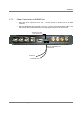


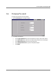


Power-up and Provisioning the Unit
MA-860 Installation and Configuration Guide 48
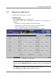
Note: If OFF is displayed, it indicates the antenna is disconnected by the system (due to a
fault such as a short.). In addition, alarms are generated.
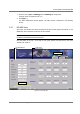
3. Perform 802.11a cable adjustments as follows:
• Set up a Constant Wave signal generator to 5.745GHz at 17dBm (for optimum
results).
Note: If the signal generator cannot be set to 17dBm, any level between 5 to 19 dBm
range will achieve good results.
• Click the corresponding Adj a button. Verify that the AP PWR and Ant PWR values of
the corresponding channel are EQUAL.
• Repeat for each link (i.e. four times).
• For each channel, verify that AP1..4 Pwr is equal to Ant1..4 Pwr.
4. Perform cable adjustments for 802.11bg as follows:
• Set up a Constant Wave signal generator to 2.447GHZ at 17dBm (for optimum
results).
Note: If the signal generator cannot be set to 17dBm, any level between 5 to 19 dBm
range will achieve good results.
• Click the corresponding Adj bg. Click the corresponding Adj a button. Verify that the
AP PWR and Ant PWR values of the corresponding channel are EQUAL.
• Repeat for each link (i.e. four times).
• For each channel, verify that AP1..4 Pwr is equal to Ant1..4 Pwr.
5. Click Apply to save adjustment and to save any changes in the DC settings
of the ports.
5.8 What next?
After performing the adjustment procedure:
Click the Alarms tab. Referring to the following section ( 5.9) do the following:
• Disable (filter out) irrelevant alarms (where antennas or APs are not connected).
• Verify that the connected Access Point and antenna indicators are Green.
• Verify that the calibration indicators are Green.