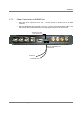
Installation 4.7.2 Power Connections to MA860 Unit • Only Main PS is connected to the unit – connect directly to 20-48V side of the PWR connector. • Main and Redundant PSs connected to the unit – connect the provided splitter cable to the unit and the Main and Redundant PSs to the appropriate connectors as shown below.
5 Power-up and Provisioning the Unit Upon power-up, MA-860 automatically performs WCE, WiFi Coverage Expander auto-discovery. It is recommended to locally connect to the unit using a computer running the telnet session to configure the local configuration options defined below.
Power-up and Provisioning the Unit 5.2 System Setup Configuration Before deploying the device in the field, it is recommended that all system level configurations are configured on the 860 WLAN module as defined in section 5.2 5.2.1.1 Assigning Network Parameters The unit is factory set with the following static IP address: IP address: 192.168.1.1 Subnet mask: 255.255.0.0 Default GW: 192.168.254.254 • Change the static address using Telnet as described in section 5.2.1.
Power-up and Provisioning the Unit 8. You will be are prompted to set the Gateway, Netmask, telnet Config password and to Change the DHCP device name. IP Address : (000) .(000) .(000) .(000) Set Gateway IP Address (Y) ? Gateway IP Address : (192) .(168) .(010) .(245) Netmask: Number of Bits for Host Part (0=default) (16) Change telnet config password (N) ? Change DHCP device name (not set) ? (N) ? 9. Press Enter to run through the rest of the parameters.
Power-up and Provisioning the Unit 5.3 Default Login and User Account Levels You may login to the MA 860 unit through any Web browser or 860 WLAN Engineering GUI. The available login credentials and default passwords are defined below: • Operator (oper) – monitoring options only • Field Engineer (eng) – monitoring and configuration options • TechSuport – for MA technical personnel only NOTE: The password is case sensitive – use lower case letters. 5.
Power-up and Provisioning the Unit 3. Select the User (Oper or Field Eng) where Field Eng has configuration privileges. Enter the password (see 5.3.) 4. Click Login. () The Main configuration window appears. The Main window is described in the following section. 5.4.1 MA 860 View Upon login, the MA-860 View shows the General tab that provides general information on the MA860 unit and on the WCE connections on each channle.
Power-up and Provisioning the Unit Table 5-1. MA 860 View Menu Options 5.5 Menu Option Description Installation User definable unit identification parameters and read-only IP address and MAC address. Security Password change options. Control Shows the General, Adjustment and Alarms tab in the bottom window area. General Unit identification and version information, and WCE information for each channel. Adjustments Unit adjustment pane. Used to calibrate cables.
Power-up and Provisioning the Unit 5.6 Changing Password To change the password of the User Name: 1. Click the Security tab in the Main window. 2. To change the password: • In the Login Password field, enter the password to login to the current session. • In the User Name field, select the User Name whose password is to be changed. • In the New Password field, enter the new password. • In the Verify Password field, type the new password again. • Click Apply.
Power-up and Provisioning the Unit 5.7 Web Access Adjustment The default gain for each channel is set to 0dB. To adjust the gain 1. Click the Adjustment button in the Main window. The window is divided areas corresponding to each channel.
Power-up and Provisioning the Unit Note: If OFF is displayed, it indicates the antenna is disconnected by the system (due to a fault such as a short.). In addition, alarms are generated. 3. Perform 802.11a cable adjustments as follows: • Set up a Constant Wave signal generator to 5.745GHz at 17dBm (for optimum results). Note: If the signal generator cannot be set to 17dBm, any level between 5 to 19 dBm range will achieve good results. • Click the corresponding Adj a button.
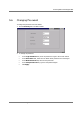
Power-up and Provisioning the Unit 5.9 Monitoring Alarms To monitor MA860 status Click the Alarms button in the Main window. The Alarms pane appears. The pane is divided into four areas corresponding to each channel and a fifth area (MA 860) for the unit as a whole. Figure 5-4. Alarms Window To disable trap monitoring of irrelevant channels For irrelevant channel, disable the Trap Select field.
Power-up and Provisioning the Unit Trap descriptions Trap Description Temp RED - temperature is above 60C; otherwise GREEN. AP a RED – 802.11a port or AP is not detected; otherwise GREEN AP bg RED – 802.11b/g port or AP is not detected; otherwise GREEN MA860 ANT RED - WCE not detected; otherwise GREEN. WCE Antenna RED – antenna connected to WCE is not detected; otherwise GREEN. DC RED - Antenna disconnected due to detected overcurrent or overcurrent detected a the antenna Adjust a RED – 802.
Power-up and Provisioning the Unit 5.10 Provisioning via the MA-860 Engineering Tool This procedure is performed via a local connection to a computer running the MA-860 Engineering Tool application. 5.10.1 Opening a Session to the Unit To provision the MA-860 control unit using the Configuration Tool 1. Install the MA-860 MA Engineering Tool application on your computer. 2. Connect to the MA-860 front panel Local connector using the RS232 9-pin cable provided with the MA-860 unit.
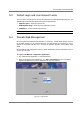
Power-up and Provisioning the Unit 3. Launch the MA-860 Engineering Tool application on the computer. The Login dialog is invoked. 4. Select Field Eng, and enter the corresponding Password (eng). 5. Select the COM Port corresponding to the physical COM port on the computer to which the unit is connected.
Power-up and Provisioning the Unit 6. Click Connect. The application main window appears with the General tab displayed by default. The General tab provides SW and HW information for the MA 860 unit and for each WCE. If the antenna discovery process has not been completed, you will see a message indicating antenna discovery is in process – as illustrated below.
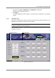
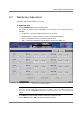
Power-up and Provisioning the Unit 5.10.2 Provisioning Procedure Note: Refer to 6.1 and Table 6-1 for the locations and descriptions of the parameters described in this section. To provision the unit 1. Select the Adjustment tab. The following window appears. Step 5. Calibrate bg. Step 4. Click a Step 3. ON Step 2. Click to discover connected antennas Step 1 Invoke Adjustment tab Step 6. Review Alarms NOTE: The Full Discovery button checks for each and every antenna.
Power-up and Provisioning the Unit • Set up a Constant Wave signal generator to 5.745GHz at 17dBm (for optimum results). Note: If the signal generator cannot be set to 17dBm, any level between 5 to 19 dBm range will achieve good results. • Click the corresponding Adj a button. The adjustment status will be indicated by the color of the button: BLACK – not adjusted or waiting for connection. Try again. YELLOW – adjustment in process. GREEN – successful adjustment. RED – adjustment failure.
Power-up and Provisioning the Unit To disable trap monitoring of irrelevant channels For irrelevant channel, disable the Trap Select field. Status color codes Each status is color codes as follows: • Green • RED • GREY - OK - Fail - Not relevant. Trap descriptions Trap Description Temp RED - temperature is above 60C; otherwise GREEN. AP a RED – 802.11a port or AP is not detected; otherwise GREEN AP bg RED – 802.
Appendix 6 Appendix 6.1 Adjustment Tab Parameters This tab is used to: • Configure the antennas manually and perform auto-discovery of antennas • Perform cable adjustment for each channel • View the power level at each antenna port and at each AP port • Reset the MA-860 unit Table 6-1. MA-860 Engineering Tool Window Parameter Descriptions Window Item Description DC Used to show and configure status of voltage at each antenna port.
Appendix Window Item Description Adj a/bg Used to perform cable adjustment for 802.11a and 802.11/bg services. Note: this is a required configuration procedure. The color of the buttons indicate the status of the corresponding adjustment procedure: Black – adjustment not initiated or communication error during the adjustment. Yellow – adjustment in process Green – successful adjustment Red – failed adjustment Antenna Power Power supplied to the antenna AP Power AP1..4 .11a – shows the 802.
Appendix 6.2 Using the Lantronix Device Installer NOTE: Be sure the installed version is 3.6 or higher. 6.2.1 Installing and Navigating the Application NOTE: Be sure the installed version is 4.1.0.3 or higher. 1. Install the Lantronix DeviceInstaller application on your computer and launch the application. The DeviceInstaller Main window appears. Figure 6-1. DeviceInstaller Main Window 2. In the toolbar, click Search to perform auto-discovery.
Appendix 6.2.2 Assigning Dynamic IP with DHCP Note: Refer to the previous section for instructions on installing and navigating the required application. 1. Select the MA860 unit and click the icon Assign IP in the toolbar. Figure 6-2. Assigning Static IP Address 3. The IP Address Assignment Method window appears. Figure 6-3. IP Assignment Method Window 4. Select Obtain an IP Address automatically – do NOT select Assign a specific IP address. Then, click Next. The IP Discovery Settings window appears.
Appendix Figure 6-4.Automatic IP Discovery Settings Window 5. Enable the following checkboxes: DHCP, BOOTP, Auto-IP and Clear Gateway. 6.. Click Next. The Assignment window appears. 7. Click Assign to assign the MA860 unit the defined parameters. Once the parameters have been assigned, the message ‘Completed Successfully’ appears and the Finish button is enabled. Figure 6-5. Finish Static IP Address Definition 8. Click Finish.
Appendix 6.3 SNMP Management Using a Standard SNMP Manager The MA 860 packages provide MIBSs that enable standard SNMP (Version 2.0) managers such as HP OpenView to view event traps sent by the MA 860 unit and to configure the unit. NOTE: These traps provide a general indication of the type of failure. The MA MA 860 enables identifying the source of the problem and system monitoring parameters. (Trap destinations and community names were defined in section 5.2.1.3. 6.3.
Appendix Name Type Severity OID Description ma860WceDCFault NOTIFICATION-TYPE major 81.4.2.0.11 DC OFF disconnected by system due to falure ma860WceDCOn NOTIFICATION-TYPE info 81.4.2.0.12 DC ON Ma860adjust11aFailed NOTIFICATION-TYPE minor 81.4.2.0.13 Adjustment on type 802.11 a Failed Ma860adjust11aSuccess NOTIFICATION-TYPE info 81.4.2.0.14 Adjustment on type 802.11 a Succeeded Ma860adjust11bgFailed NOTIFICATION-TYPE minor 81.4.2.0.15 Adjustment on type 802.
Appendix 6.3.2 Viewing and Configuring Using a Standard MIB Browser To view and configure using any standard SNMP manager NOTE: It is assumed that the IP Address of at least one destination is already defined. From a computer configured as a trap destination (configured to receive the traps), load the MIB file to the SNMP manager. The following figure shows the MIB tree that includes the loaded MobileAccess MA 860 file. Figure 6-6.