
User's Manual

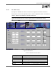

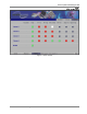
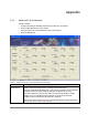

Table Of Contents
- Preface Material
- Product Certifications
- Company Certification
- Introduction to the MA-860 System
- Element Descriptions
- Infrastructure Preparation
- Installation
- Power-up and Provisioning the Unit
- Appendix

Appendix
MA-860 Installation and Configuration Guide 47
Window Item Description
Calib a/bg Used to perform cable adjustment for 802.11a and 802.11/bg services.
Note: this is a required configuration procedure.
The color of the buttons indicate the status of the corresponding adjustment
procedure:
Black – adjustment not initiated or communication error during the adjustment.
Yellow – adjustment in process
Green – successful adjustment
Red – failed adjustment
Antenna Power Power supplied to the antenna[MP14]
General area Curr Ant 1..4 – the current value indicates whether the corresponding antenna is
operating normally.
AP Power AP1..4 .11a – shows the 802.11a service power provided by the corresponding (1 to
4) AP.
Note: During normal operation, this value should be equal to the power
transmitted by the relevant antenna (parameter Pwr 11.a of the corresponding
antenna*).
AP1..4 .11b/g – shows the 802.11b/g service power provided by the corresponding
(1 to 4) AP.
Note: During normal operation, this value should be equal to the power
transmitted by the relevant antenna (parameter Pwr 11.b/g of the corresponding
antenna*).
Antenna 1..4 Four window areas corresponding to each antenna.
Only the areas of antennas
detected during auto-discovery (automatically performed when power is connected)
are accessible
. Each area contains the following parameters:
o Pwr .11a – 802.11a service power measured at antenna output. Should be the
same as the 802.11a service power output by the corresponding AP (AP .11a
under AP Pwr).
o Pwr .11bg – 802.11b/g service power measured at antenna output. Should be the
same as the 802.11b/g service power output by the corresponding AP (AP .11b/g
under AP Pwr) *.
o AP a DCA – Digital Control Attenuator for 802.11a Tx/Rx antenna Gains. Used to
manually attenuate (reduce) the signal under special conditions of Cable
Adjustment failure.
The greater the DCA value, the smaller the signal.
o AP bg DCA – Digital Control Attenuator for 802.11b/g Tx/Rx antenna Gains. Used
to manually attenuate (reduce) the signal under special conditions of Cable
Adjustment failure.
The greater the DCA value, the smaller the signal.
o N/Tx 11a – power level of 802.11a signal transmitted by the antenna. Should be
preset to “Normal” mode (Tx mode is used only for factory testing).
o 5V .11a – input voltage for the TDD Amplifier of 802.11b/g
o 5V .11bg – input voltage for the TDD Amplifier of 802.11b/g (normal values are 4-
5V)
o 3V – input voltage level for 802.11a Rx
o 6V – Antenna Input DC Power
o 3.3V – Digital Control voltage level
*This is relevant only AFTER the adjustmet procedure is performed.