
User's Manual
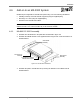
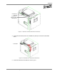
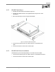


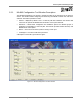
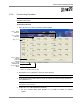
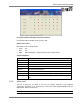
Table Of Contents
- Preface Material
- Product Certifications
- Company Certification
- Introduction to the MA-860 System
- Element Descriptions
- Infrastructure Preparation
- Installation
- Power-up and Provisioning the Unit
- Appendix

Power-up and Provisioning the Unit
MA-860 Installation and Configuration Guide 37
Note: If the signal generator cannot be set to 17dBm, any level between 5 to 19 dBm range will
achieve good results.
• Click the corresponding Calib a. The adjustment status will be indicated by the color of
the button:
GREY – not adjusted or waiting for connection. Try again.
YELLOW – adjustment in process.
GREEN – successful adjustment.
RED – adjustment failure. Try again.
• Repeat for each link (i.e. four times).
• Verify that AP1..4 .11a (under AP) are equal to Pwr 11.a of the corresponding
antenna.
5. Perform cable adjustments for 802.11bg as follows:
• Set up a Constant Wave signal generator to 2.447GHZ at 17dBm (for optimum
results).
Note: If the signal generator cannot be set to 17dBm, any level between 5 to 19 dBm range will
achieve good results.
• Click the corresponding Calib bg. The adjustment status will be indicated by the color of
the button:
GREY – not adjusted or waiting for connection. Try again.
YELLOW – adjustment in process.
GREEN – successful adjustment.
RED – adjustment failure. Try again.
• Repeat for each link (i.e. four times).
• Verify that AP1..4 .11bg (under AP) are equal to Pwr 11.bg of the corresponding
antenna.
6. Click the Alarms tab. Referring to the following section (
5.5).
• Disable (filter out) irrelevant alarms (where antennas or APs are not connected).
• Verify that the connected Access Point and antenna indicators are Green.
• Verify that the calibration indicators are Green.